Systems and Methods for Converting Cryogenic Liquid Natural Gas to High Pressure Natural Gas and to Low Pressure Natural Gas and Retain All Converted Product and To Further Dispense Only By Voluntary Actions of the User

Active Publication Date: 2018-05-03
ANDERSON KENNETH W
View PDF11 Cites 2 Cited by
  • Summary
  • Abstract
  • Description
  • Claims
  • Application Information

AI Technical Summary

Benefits of technology

The present invention is a system for gasifying cryogenic liquid, such as liquefied natural gas (LNG), to a warm gas for use as fuel in vehicles and for hydrogen production. The system uses a two-stage process where the cryogenic liquid is first converted to a gas and then warmed to a temperature close to its ambient temperature. This results in a more homogeneous fuel that does not contain impurities. The system can be scaled up or down depending on the desired volume and pressure of the gas. It uses a unique design with high-density gasification containers and a separate container for dispensing the gas. The system is cost-effective and can be easily installed and operated.

Problems solved by technology

Some specifications of containers do not allow high pressure, such as LNG Storage tanks where the design is such to preserve a cryogen for a month at a time by increasing insulation and decreasing thermal transfer by reducing the thickness of the container, which limits strength for containing pressure.

Method used


Image

  • Systems and Methods for Converting Cryogenic Liquid Natural Gas to High Pressure Natural Gas and to Low Pressure Natural Gas and Retain All Converted Product and To Further Dispense Only By Voluntary Actions of the User
  • Systems and Methods for Converting Cryogenic Liquid Natural Gas to High Pressure Natural Gas and to Low Pressure Natural Gas and Retain All Converted Product and To Further Dispense Only By Voluntary Actions of the User
  • Systems and Methods for Converting Cryogenic Liquid Natural Gas to High Pressure Natural Gas and to Low Pressure Natural Gas and Retain All Converted Product and To Further Dispense Only By Voluntary Actions of the User

Examples


Embodiment Construction

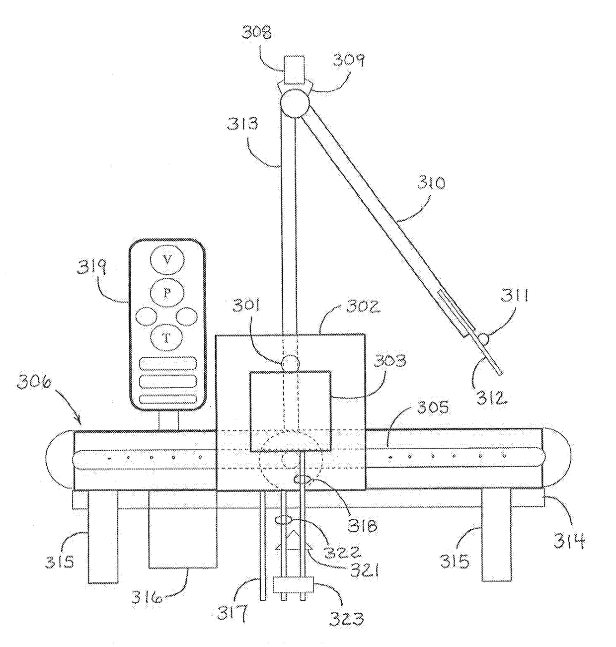
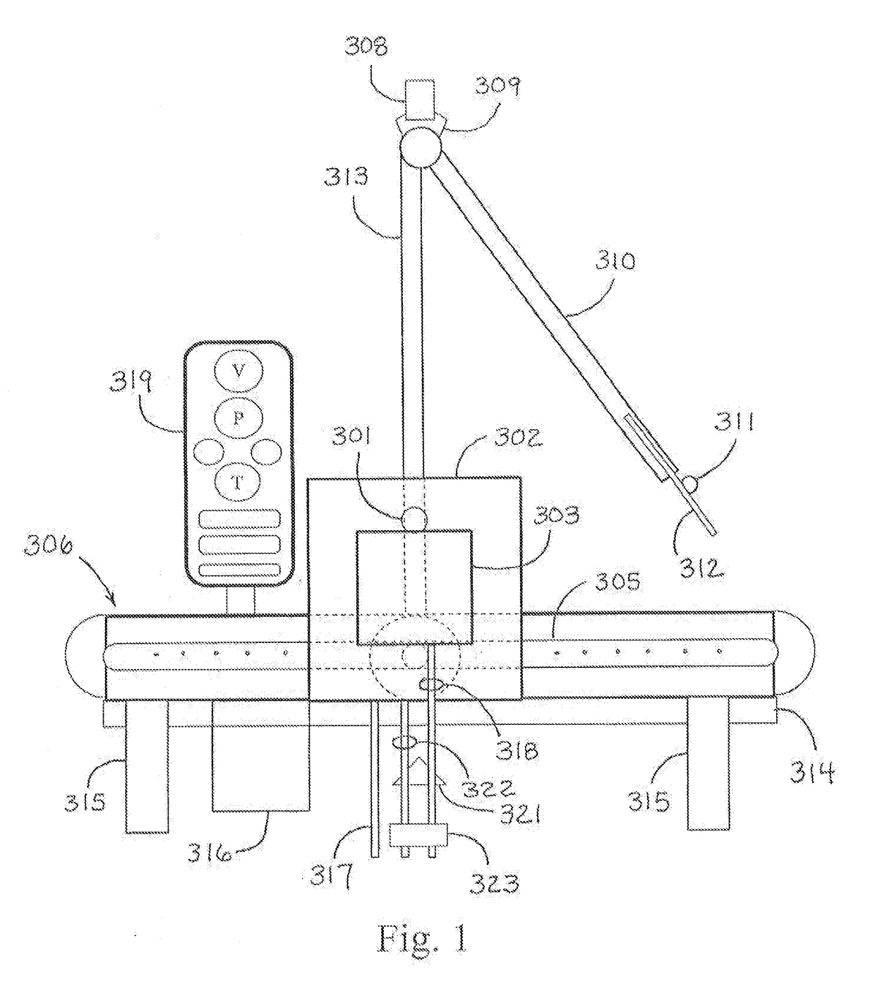
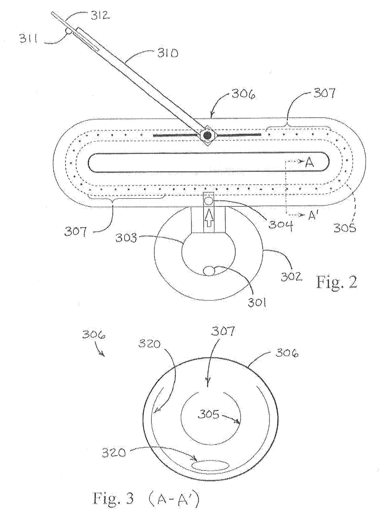
[0053]The present invention provides a LNG to CNG to NG system and method. This system may be optionally enhanced by a system generating hydrogen gas such as an electrolysis at pressure and / or at depth system. The system may also be optionally enhanced by a steam and methane reformation system, including as a heat exchange mechanism described. In the system of FIGS. 1 & 2, an oval CNG expansion chamber 2.4 times the size of the LNG cryogenic container is provided with center tube circles vented. High nickel alloy steel and some layered composites and aluminum alloys are preferably used in the construction of this system where there is contact with cryogenic liquids. The system further may include passive and / or active heat sinks. The system includes LNG fill portal 301 for the cryogenic like vessel. Also disclosed are outer container 302 and inner container 303 for the LNG Again, the approximate ratio of the container volume being 1:2.4 (41.6%) to the volume of oval pressure vessel ...


PUM


Abstract

A system to convert and dispense pressurized gas(es) of cryogenic liquids of gas(es), and systems and methods to efficiently convert liquid natural gas (LNG) to compressed natural gas (CNG) and low pressure natural gas (NG) and other cryogenic liquids of gas. The system requires one dedicated pressure vessel of horizontal and vertical elements at the dispensing location to convert, retain, store, and dispense multiple pressures of gas from a cryogenic liquid supply such as a non-dedicated high pressure cryogenic personal supply tank. The system efficiently modifies and controls parameters of volume, pressure, and temperature in conversion scale to retain all converted product under human control to dispense without process required waste for use in commercial, industrial, and in particular single family residential applications and service can be accomplished by pickup truck and trailer, where semi trucks, big rig trucks and process pollution are not welcome.

Description

CROSS REFERENCE TO RELATED APPLICATIONS[0001]This application is a continuation-in-part of U.S. patent application Ser. No. 14 / 397,457, filed Oct. 27, 2014, entitled “Systems and Methods for Converting Liquid Natural Gas to Compressed Natural Gas and to Low Pressure Natural Gas” which claims benefit of PCT / US13 / 38291, filed on Apr. 25, 2013, entitled “Systems and Methods for Converting Liquid Natural Gas to Compressed Natural Gas and to Low Pressure Natural Gas” which claims benefit of U.S. Provisional Application 61 / 637,908 filed Apr. 25, 2012.BACKGROUND OF THE INVENTION[0002]The present invention relates generally to systems for efficiently converting batches of the cryogenic liquid of a gas into a beneficial pressurized gas such as liquid natural gas (LNG) to compressed natural gas (CNG), also known as pressurized natural gas (PNG), and further to low pressure natural gas (NG). The present invention relates more specifically to a system for efficiently modifying and controlling t...

Claims


Application Information

Patent Timeline
IPC IPC(8): F17C9/02F17C5/06
CPCF17C9/02F17C5/06F17C2201/0138F17C2201/035F17C2201/05F17C2203/0614F17C2205/0326F17C2205/0335F17C2221/012F17C2221/033F17C2223/013F17C2223/0161F17C2223/033F17C2225/0123F17C2225/036F17C2227/0393F17C2250/01F17C2250/036F17C2250/0426F17C2201/0147F17C2201/032F17C2201/056F17C2201/058F17C2203/0304F17C2203/0391F17C2203/0646F17C2203/0648F17C2205/0149F17C2205/0332F17C2221/011F17C2221/014F17C2221/016F17C2227/0302F17C2265/05F17C2270/0171F17C2270/0178F17C2270/07Y02E60/32
Inventor ANDERSON, KENNETH W.
Owner ANDERSON KENNETH W
Why Eureka
Try Eureka