Gas intake device comprising an oriented masking element

a masking element and gas inlet technology, applied in the direction of air intakes for fuel, combustion-air/fuel-air treatment, machines/engines, etc., can solve the problems of complex solution, limiting the gas and affecting the filling of the cylinder at high load

Active Publication Date: 2022-11-22
INST FR DU PETROLE
View PDF17 Cites 0 Cited by
  • Summary
  • Abstract
  • Description
  • Claims
  • Application Information

AI Technical Summary

Benefits of technology

[0017]It is an object of the invention to overcome these disadvantages, by means of an inlet device able, in a simple way, to obtain good engine performance, notably with significant turbulent energy and a stable swumble-type aerodynamic structure of the gas. In order to do that, the present invention relates to a gas inlet device for a cylinder of an internal combustion engine. The gas inlet device comprises an inlet port, an inlet valve, a valve seat of the inlet valve, means for forming a tumble-type aerodynamic movement of the gas within the cylinder, and a mask. Furthermore, the intersection between the inlet port and the valve seat is along a straight line not parallel to the plane of the firing face. This inclination allows the generation of an aerodynamic movement of the swirl type in the cylinder, which combines with the tumble to form an aerodynamic movement of the swumble type. In addition, the mask is oriented in the same way as the end of the inlet port, encouraging the aerodynamic movement of the gas in the cylinder.

Problems solved by technology

Such a solution is complex and detrimental to the filling of the cylinder.
However, that solution requires a phase-shifting of the openings of the inlet valves, and proves detrimental at high load.
In both instances, these appendages limit the filling of the cylinder with gas.
In addition, the active appendages require control, making the solution complex.
However, in order to obtain a swumble-type aerodynamic movement of the gas, it would appear necessary to use two masks per inlet port, or to use special valve-lift laws, making this solution complex.
In addition, the masks used limit the filling of the cylinder with gas.

Method used


Image

  • Gas intake device comprising an oriented masking element
  • Gas intake device comprising an oriented masking element
  • Gas intake device comprising an oriented masking element

Examples


examples

[0092]The features and advantages of the method according to the invention will become more clearly apparent on reading the following comparative example.

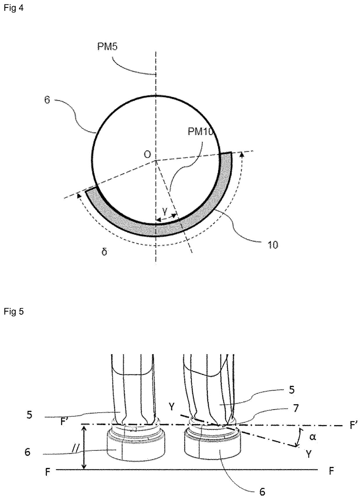
[0093]In this comparative example, a comparison is made between two inlet devices with identical means for generating a swumble-type aerodynamic movement and with masks in the shape of an annulus portion extending over an angular portion of 170°. In the first inlet device compared, the mask is oriented in accordance with the prior art (FIG. 3). In the second inlet device compared, the mask is oriented according to one embodiment of the invention (FIG. 4) with α=15° and γ=15°.

[0094]FIGS. 6 and 7 are views from above (in the operational position) of a cylinder 13 equipped with two inlet ports each provided with a mask 10 and with two exhaust ports 12. FIGS. 6 and 7 illustrate the aerodynamic movement of the gas 11 for a crankshaft angle of 460°, corresponding to the start of the induction stroke. FIG. 6 corresponds to the setup accor...


PUM


Abstract

The present invention relates to a gas inlet device (1) for a cylinder of an internal combustion engine. The gas inlet device (1) comprises an inlet port (5), an inlet valve (4), a calibration (6) of the inlet valve (4), means for forming a tumble-type aerodynamic movement of the gas in the cylinder, and a mask (10). Furthermore, the intersection (7) between the inlet port (5) and the calibration (6) is along a straight line not parallel to the plane of the firing face (FF). In addition, the mask (10) is oriented in the same way as the end of the inlet port (5).

Description

CROSS-REFERENCE TO RELATED APPLICATIONS[0001]This application is a U.S. national phase application filed under 35 U.S.C. § 371 of International Application No. PCT / EP2020 / 058714, filed Mar. 27, 2020, designating the United States, which claims priority from French Patent Application No. 19 / 04.025 filed Apr. 16, 2019, which are hereby incorporated herein by reference in their entirety for all purposes.TECHNICAL FIELD[0002]The present invention relates to the field of gas inlet devices for an internal combustion engine. The present invention relates in particular to gas inlet devices capable of generating an aerodynamic movement of gases in the cylinder of the engine.[0003]This type of engine generally comprises at least one cylinder, a piston sliding in this cylinder in a reciprocating rectilinear movement, means for admitting an oxidant, means for exhausting burnt gases, a combustion chamber, and injection means for injecting a fuel.[0004]As is generally acknowledged, when designing...

Claims


Application Information

Patent Timeline
Patent Type & Authority Patents(United States)
IPC IPC(8): F02B31/08F02F1/42F02M35/10F02B31/04F02B23/10F02B31/00
CPCF02B31/085F02B31/04F02F1/4235F02M35/10124F02B2023/103F02B2023/106F02B2023/108F02B2031/006F02B2275/48F02M35/1085Y02T10/12
Inventor GAUTROT, XAVIERTROST, JULIENRITTER, MARTINKRIEGER, ARNAUDLUCA, PAUL-GEORGIAN
Owner INST FR DU PETROLE
Why Eureka
Try Eureka