Foil strain gage for automated handling and packaging

Active Publication Date: 2005-02-24
VISHAY MEASUREMENTS GROUP
View PDF19 Cites 2 Cited by
  • Summary
  • Abstract
  • Description
  • Claims
  • Application Information

AI Technical Summary

Benefits of technology

The present invention provides for a strain gage that is simpler to manufacture, handle and install. The strain gage includes a semi-rigid substrate having a thickness of 3 to 30 mils and a resistive strain sensitive foil bonded to the semi-rigid substrate, and a first and a second terminal operatively connected to the resistive foil. The resistive foil and semi-rigid substrate and their geometrical relationship are selected to provide a strain sensitivity greater than 50 percent of the strain sensitivity of the resistive foil. Because a semi-rigid substrate is used, the strain gage is easier to handle and to install.
The strain gage can include an anti-static layer attached to a surface of the semi-rigid substrate which further makes the strain gage conducive to handling. The anti-static layer also facilitates soldering the strain gage to a metal part.
According to another aspect of the present invention, a method of performing the final strain gage manufacturing steps is provided, which greatly reduces manufacturing labor content over prior art. The method takes advantage of modern automated equipment with resistance checking, optical inspection, and tape and reel packaging commonly employed when manufacturing electronic components. Prior art strain gages are not compatible with such modem automated equipment because they are fragile and susceptible to clinging caused by static electricity.

Problems solved by technology

Prior art strain gages are not compatible with such modem automated equipment because they are fragile and susceptible to clinging caused by static electricity.

Method used


Image

  • Foil strain gage for automated handling and packaging
  • Foil strain gage for automated handling and packaging
  • Foil strain gage for automated handling and packaging

Examples


Embodiment Construction

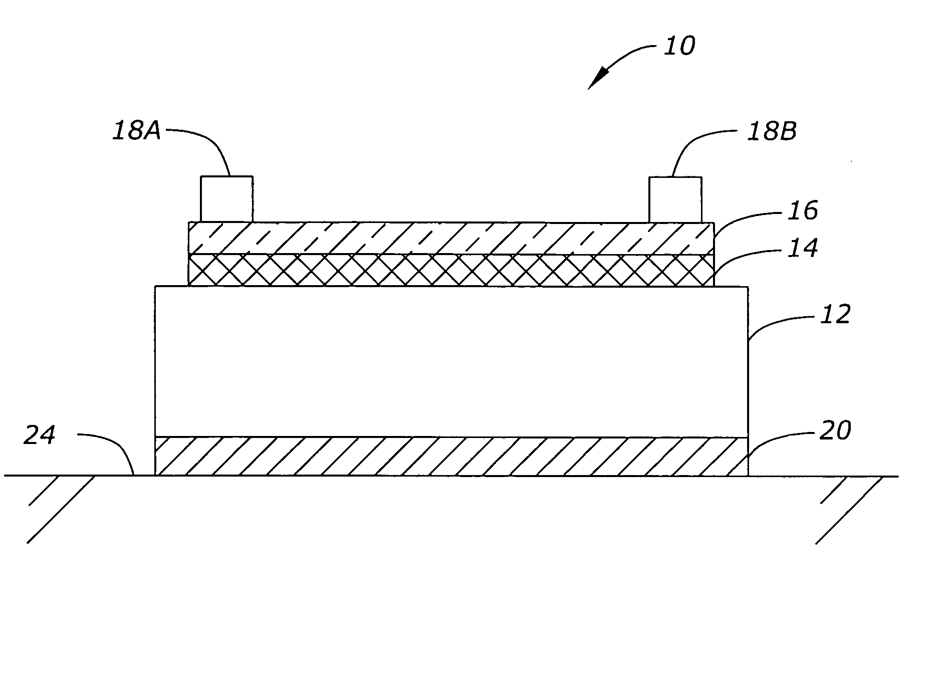
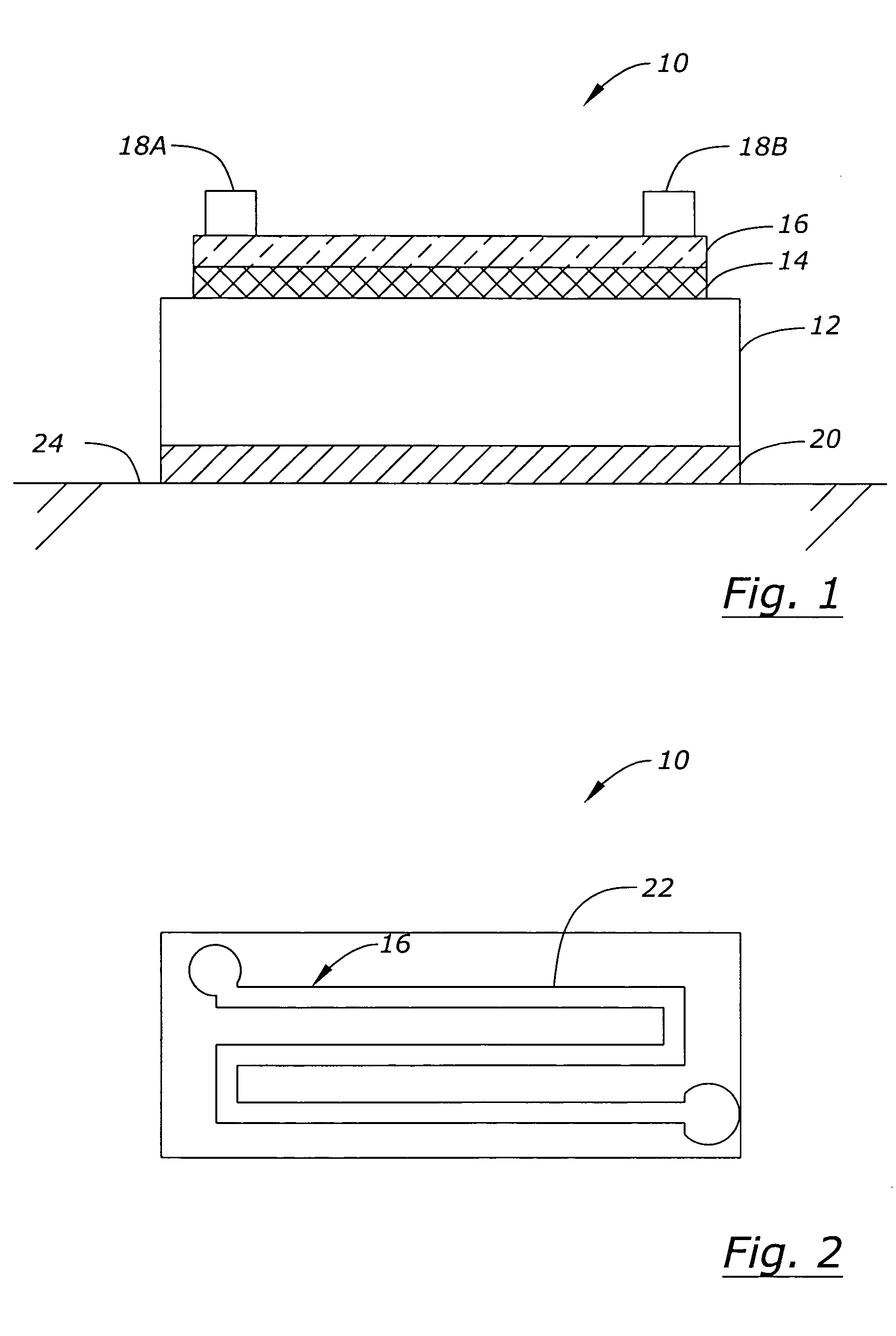
The present invention relates to strain gages. In particular, the present invention relates to providing a strain gage that is semi-rigid and not flexible in order to avoid the disadvantages of the prior art. The strain gage of the present invention is suitable for use on flat or slightly curved surfaces and provides advantages in ease of manufacturing and installation.

The strain gage includes the same type of serpentine resistive foil pattern associated with prior art strain gages, but the foil pattern is bonded to a semi-rigid substrate made of fiberglass, or polyimide resin, or other stiff material 3 mils to 30 mils in thickness. Substrate stiffness is a function of material modulus of elasticity (E) and thickness (t). The sensitivity of the strain gage to strain, k, remains greater than 50 percent of the strain sensitivity of the resistive foil despite the thickness and rigidity of the device. For example: 1. For resistive foil composed of Cu—Ni or Ni—Cr with a normal strain...


PUM


Abstract

An improved strain gage and an improved manufacturing method are disclosed. The strain gage includes a semi-rigid substrate having a thickness of 3 to 30 mils, a resistive strain sensitive foil bonded to the semi-rigid substrate for providing a resistance varying with strain associated with a surface to which the strain gage is attached, a first and a second terminal operatively connected to the resistive strain sensitive foil, and an anti-static layer. The improved strain gage allows for reduced labor content in manufacturing by allowing use of modern automated electronic component manufacturing equipment.

Description

BACKGROUND OF THE INVENTION The present invention relates to strain gages. A strain gage is a strain sensitive resistive device used to measure mechanical strain. A strain gage is typically adhesively bonded to a surface and then measured changes in the resistance of the strain gage are associated with various effects depending upon the configuration of the strain gage. Strain gages can be used to measure bending, axial and torsional load or other strain effects. A strain gage is made of a resistive foil which is typically photoetched, ion milled, or otherwise cut to form a pattern to produce a resistance. Foil material is usually a Cu—Ni or Ni—Cr alloy of 50 microinches to 200 microinches in thickness. A typical resistance value associated with a strain gage is 120 ohms. The foil pattern is usually bonded to a very thin flexible polymer backing with an epoxy or similar resin or other cement. The polymer backing is thin (0.5 to 1.0 mils) to enhance flexibility. Such a device is str...

Claims


Application Information

Patent Timeline
IPC IPC(8): G01B7/16G01L1/18G01L1/22
CPCG01L1/2287
Inventor KIEFFER, THOMAS PATRICKWATSON, ROBERT BARRYKARCHER HARRIS, SHARON LEE
Owner VISHAY MEASUREMENTS GROUP
Why Eureka
Try Eureka