Electrostatic coating system

a coating system and electrostatic technology, applied in coatings, watering devices, light and heating equipment, etc., can solve problems such as electrical leakage inside electrostatic coating systems, and achieve the effect of continuing coating operation

Active Publication Date: 2005-02-24
CARLISLE FLUID TECH RANSBURG JAPAN KK
View PDF6 Cites 37 Cited by
  • Summary
  • Abstract
  • Description
  • Claims
  • Application Information

AI Technical Summary

Benefits of technology

[0011] It is therefore an object of the invention to provide an electrostatic coating system capable of continuing coating operation even under considerable electrical leakage.
[0012] A further object of the invention is to provide an electrostatic coating system enabling an operator to immediately locate the source of electrical leakage inside the atomizer.
[0013] A still further object of the invention is to provide an electrostatic coating system including a safety mechanism for interrupting the supply of a high voltage under a dangerous condition to keep safety of operators and capable of optimizing the control of interruption of the power supply by the safety mechanism.

Problems solved by technology

Electrical leakage inside an electrostatic coating system occurs most often in paint paths and air paths.

Method used


Image

  • Electrostatic coating system
  • Electrostatic coating system
  • Electrostatic coating system

Examples


first embodiment (figs.1-7)

[0033] First Embodiment (FIGS. 1-7)

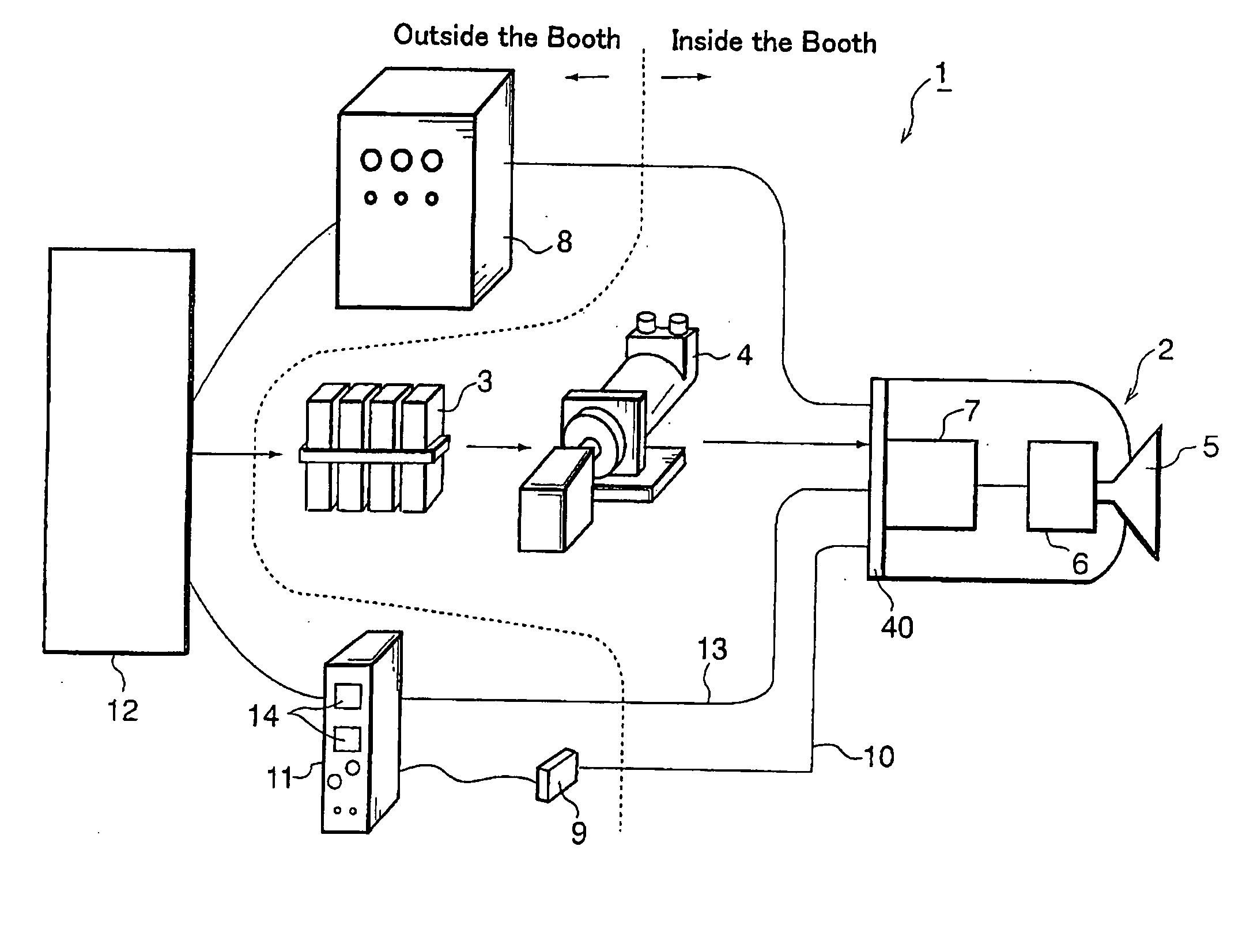
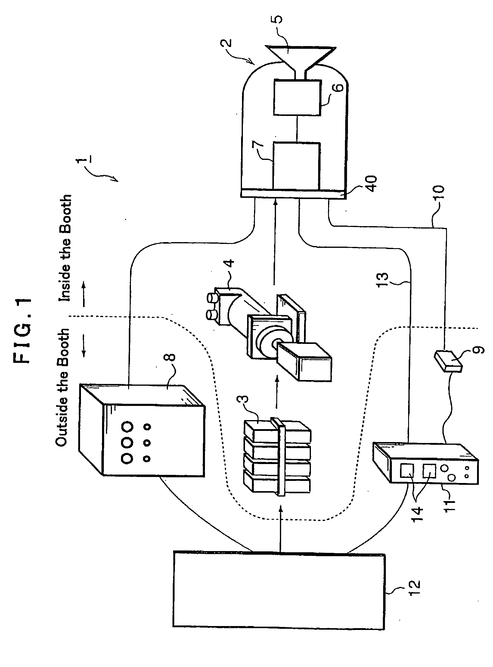
[0034]FIG. 1 shows a coating system 1 including an electrostatic atomizer 2 according to the first embodiment of the invention. The coating system 1 has a built-in high voltage generator circuit. The coating system 1 is typically incorporated in a coating line (not shown) of vehicle bodies. The atomizer 2 is of a rotary atomization type, and it is attached to a distal end of a robot arm (not shown). The paint supply system for dispensing paint to the electrostatic atomizer 2 includes a color change valve 3 and a paint pump 4.

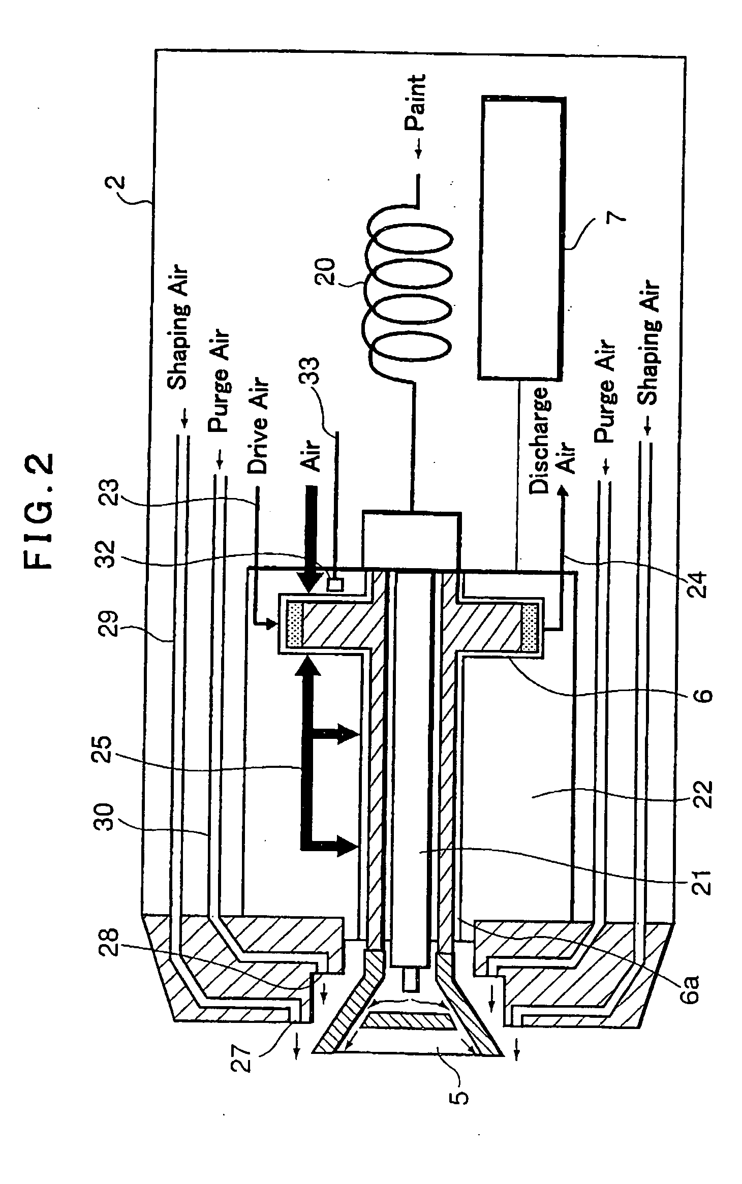
[0035] The electrostatic atomizer 2 includes an air turbine 6 for driving a rotary atomizer head 5 and a high voltage generator 7. A high voltage generated in the high voltage generator 7 is applied to the rotary atomizer head 5 that substantially functions as an electrode of the electrostatic atomizer 2. Air in the coating system, including air for driving the air turbine 6 and shaping air, is controlled by an air controller ...

second embodiment (fig.8)

[0073] Second Embodiment (FIG. 8)

[0074]FIG. 8 shows a general aspect of a coating system according to the second embodiment, including an electrostatic atomizer 201 attached to a distal end of a robot arm 200. The electrostatic atomizer 201 in this embodiment is supplied with a high voltage from an external high voltage generator 202. That is, the high voltage generated in the external high voltage generator 202 is supplied to the electrostatic atomizer 201 via a high voltage cable 204 passing through the robot arm 200. The high voltage cable 204 is comprised of a core wire 205, an insulating layer 206 covering the core wire 205 and an outer shield 207 covering the insulating layer 206.

[0075] The electrostatic atomizer 201 further includes a paint supply path 210 connected to a paint supply tube 208 via a metal joint 209. The paint supply path 210 includes a helical paint tube 211 as a part thereof.

[0076] On the back surface 201a of the electrostatic atomizer 201, a leak sensor 21...


PUM


Abstract

Total supplied current (I2) and high voltage (Vm) supplied to a rotary atomizer head (5) are detected by a total current sensor (115) and a high voltage sensor (116). Total leak current (I2) in paint paths, thinner paths and air paths inside an electrostatic atomizer (2) is detected via a metal back plate (40) of the electrostatic atomizer (2). When the total leak current value (I2) exceeds a threshold value (Ia), the level Vm of the high voltage applied to the rotary atomizer head (5) is lowered stepwise.

Description

FIELD OF THE INVENTION [0001] This invention relates to an electrostatic coating system including an electrostatic atomizer. BACKGROUND OF THE INVENTION [0002] Electrostatic coating systems including an electrostatic atomizer, in general, are configured to electrically charge paint particles with a high voltage generated by an external or built-in high voltage generator (typically of a cascade type) such that the charged paint particles are attracted onto a work held in a ground potential. The high voltage to be applied is changed in voltage value depending upon the nature of the paint to maintain the normal voltage of the atomizer at a predetermined value (for example, −90 kV). [0003] To keep the safety of operators, conventional electrostatic coating systems include a safety mechanism for interrupting operation of the high voltage generator and thereby stopping application of the high voltage before accidental short-circuiting occurs when the atomizer excessively approaches the wo...

Claims


Application Information

Patent Timeline
Patent Type & Authority Applications(United States)
IPC IPC(8): B05B5/04B05B5/053B05B5/10B05B7/08
CPCB05B5/0407B05B5/0415B05B5/10B05B5/0426B05B5/053B05B5/0422B05B5/025
Inventor NAGAI, KIMIYOSHI
Owner CARLISLE FLUID TECH RANSBURG JAPAN KK
Why Eureka
Try Eureka