Apparatus and method for producing small gas bubbles in liquids

Active Publication Date: 2005-02-24
EXTERRAN WATER SOLUTIONS ULC
View PDF11 Cites 23 Cited by
  • Summary
  • Abstract
  • Description
  • Claims
  • Application Information

AI Technical Summary

Benefits of technology

Accordingly, in a preferred method of the present invention taking advantage of the above “sorting” principle in order to obtain gas microbubbles of a size less than 100 microns, such method comprises a method for producing a liquid having gas microbubbles therein the majority of which are of a size less than 100 microns, comprising the steps of: providing gas to said liquid to form a gas/liquid mixture; directing said gas-liquid mixture into a hollow pipe member, said pipe member having a maximum interior width Di and a maximum exterior width Do, said pipe member situate proximate an upper portion of a containment vessel and extending into an interior of said containment vessel, said upper portion of said containment vessel containing said gas being under p

Problems solved by technology

As well, a lesser amount of gas, and smaller containment vessels, can thus be used, resulting in cost savings.
Disadvantageously, none of the aforementioned patents teach or disclose any specific design interrelation between the dimensions of the injector holes/parts/or gaps and the conduit outer dimensions which will best produce microbubbles in th

Method used


Image

  • Apparatus and method for producing small gas bubbles in liquids
  • Apparatus and method for producing small gas bubbles in liquids
  • Apparatus and method for producing small gas bubbles in liquids

Examples


example 1

A series of seventeen various-sized apparatus 10 were constructed in accordance with one of the embodiments of the invention as contemplated herein, namely that embodiment shown in FIG. 1, having a pair of apertures 32 in the form of horizontally-extending rectangular slots 90, as shown in FIG. 5.

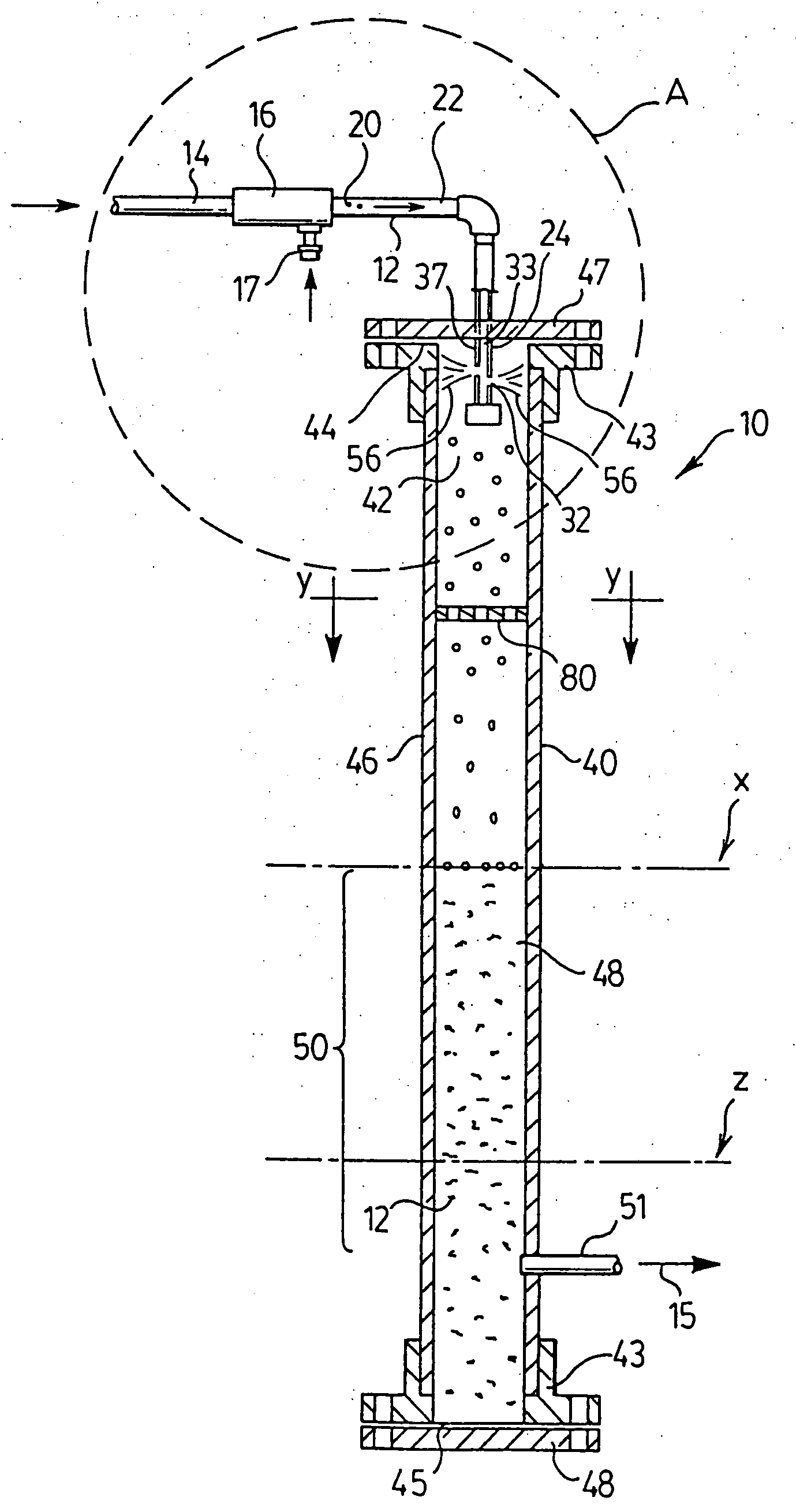
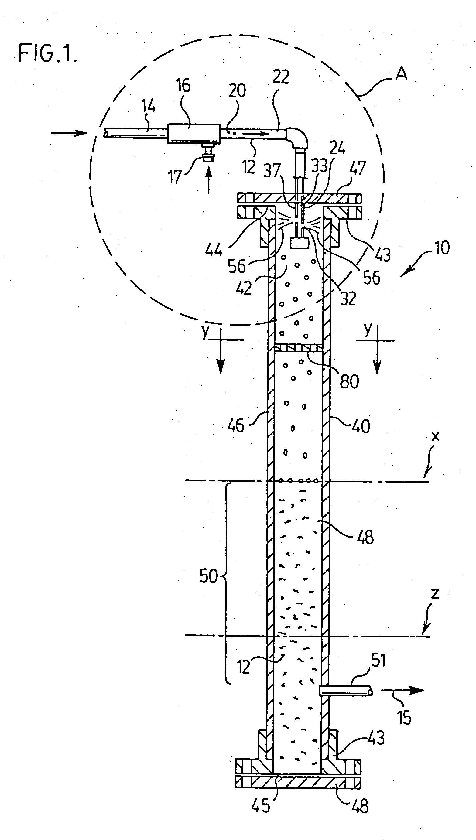
Each of the aforesaid seventeen test units comprised a shell (referred to above and below as a vessel 40), having in an upper portion 42 thereof a downwardly extending, substantially vertical cylindrical pipe member 24 of various Di and Do, ranging from nominal pipe nominal diameters of 0.50 inches to 10.0 inches.

Each of pipe members 24 for the various test units had a pair of rectangular opposed slots 90 therein, as shown in FIG. 5. The exit area Ae for the pair of slots was set as the maximum, in accordance with the requirement Ae(max)=Ai×Di / Do. Because the width of each of the slots 90 was the width Di of each pipe member 24 as shown in FIG. 5, the vertical depth (ie “gap”) of each ...

example 2

Purpose

The purpose of this experiment was to confirm various formula for optimum creation of microbubbles using the apparati of the present invention.

This was done by evaluating the effect of aperture size and apertures exit area on the size of the bubbles produced.

Apparatus

Apparatus of the type shown in FIG. 14 was selected, and in particular an apparatus of FIG. 14 having the dimensions for inlet pipe member OD and ID and (upper) impaction pipe length, as well as shell (vessel) height and diameter, as per test unit number 2 in Tables I and II.

FIG. 15 shows associated equipment used with the selected model of apparatus 10 of the present invention in conducting the above tests. A Plexiglas receiving tank 100 was utilized for receiving water having microbubbles entrained therein from apparatus 10 and to permit observation of bubble rise to permit calculation of bubble velocity (used to determine bubble size). A ruler 102 was attached to the outside of the tank to allow form...


PUM

PropertyMeasurementUnit
Lengthaaaaaaaaaa
Pressureaaaaaaaaaa
Pressureaaaaaaaaaa

Abstract

An apparatus for creating microbubbles of gas in a liquid, and for using such created microbubbles to purify said liquid of undesirable materials therein. A vertical pipe member is adapted to receive a liquid-gas mixture having gas bubbles of relatively large diameter therein. A series of horizontally-extending apertures are provided to permit the pipe member to expel such liquid-gas mixture radially outwardly from such pipe member. A plug means is provided in a lowermost distal end of the pipe member, so that such liquid-gas mixture is only expelled horizontally outwardly. The expelled liquid-gas mixture may contact the sides of a containment vessel. A baffle may further be provided in such containment vessel. In a refinement of the invention, a specific relationship is further specified between the exit area of the apertures and the interior cross-sectional area of the pipe member, in order to most suitably convert the gas bubbles in such liquid-gas mixture to microbubbles of a desired small size when expelled under pressure from such pipe member via such apertures. A limitation on the aperture maximum dimension, as a function of the pipe interior cross-sectional area and outer circumference, is also disclosed. A method of converting gas bubbles in such liquid-gas mixture to gas microbubbles, and for exposing such gas microbubbles to material entrained in such liquid-gas mixture so as to permit such gas microbubbles to physically or chemically react with such materials, is further disclosed.

Description

FIELD OF THE INVENTION The present invention relates to an apparatus and method for aeration and purification of liquids, and more particularly to an apparatus and method for producing small gas bubbles in liquids for purification and aeration of said liquids. BACKGROUND OF THE INVENTION Entrainment of a gas in a liquid is required in numerous industrial processes, typically for the purposes of reacting the gas with such liquid or materials in such liquid, such as dissolved ions or finely dispersed solids, to cause reaction of such gas with materials therein to cause same to be neutralized by, react with, or precipitate or be filtered out of such liquid. For example, it is known to bubble ozone through water, to allow the ozone to react and combine with dissolved minerals and / or finely dispersed solids within the water, so as to form solid products which may either precipitate out of the liquid or be filtered from the water, so as to thereby purify the water. The ozone may furthe...

Claims


Application Information

Patent Timeline
IPC IPC(8): B01F3/04B01F3/08B01F5/02C02F1/74C02F1/78F24F8/10
CPCB01F3/04049Y10S261/75B01F3/0876B01F5/0268B01F5/0415B01F5/0682B01F5/0688B01F5/106B01F5/20B01F2215/0052C02F1/74C02F1/78F24F3/1603F24F2003/1667B01F3/04496F24F8/10F24F8/22B01F23/2132B01F23/2322B01F23/454B01F25/25B01F25/3121B01F25/45B01F25/4521B01F25/53B01F25/72B01F2101/305
Inventor LEE, DOUGLASSZILAGYI, DENNIS NICHOLAS
Owner EXTERRAN WATER SOLUTIONS ULC
Why Eureka
Try Eureka