Device for transmitting signals between movable units

a technology of moving units and transmitting signals, which is applied in the direction of leaky waveguide antennas, waveguides, antennas, etc., to achieve the effects of small mechanical stability, higher stability, and small mechanical stability

Inactive Publication Date: 2005-02-24
MICROSOFT CROPORATION
View PDF15 Cites 10 Cited by
  • Summary
  • Abstract
  • Description
  • Claims
  • Application Information

AI Technical Summary

Benefits of technology

[0035] An especially advantageous embodiment of the invention consists in a dielectric that encloses air and therefore is of only small mechanical stability being combined with at least one second insulating material to give a massive type of construction of correspondingly higher stability. Thus, this second insulating material can be used to stabilize a combination of various dielectrics. This makes possible a precise fixing of the position of the dielectrics which is absolutely necessary for high symmetry, irrespective of the poorer mechanical properties of the first layer.
[0036] In another advantageous embodiment of the invention, the second layer is designed to be a mechanically rigid layer in order to fix or stabilize the first layer to which it is joined. A joining of this kind can be effected, for example, by form-locking or also by means of an adhesive. With an embodiment of this kind, not only a higher stability, but also a precisely defined geometry is obtained. In addition, the fabri

Problems solved by technology

The problem arises of providing a broadband and low-cost device for signal transmission, that has a conductor arrangement with conduc

Method used


Image

  • Device for transmitting signals between movable units
  • Device for transmitting signals between movable units
  • Device for transmitting signals between movable units

Examples


Embodiment Construction

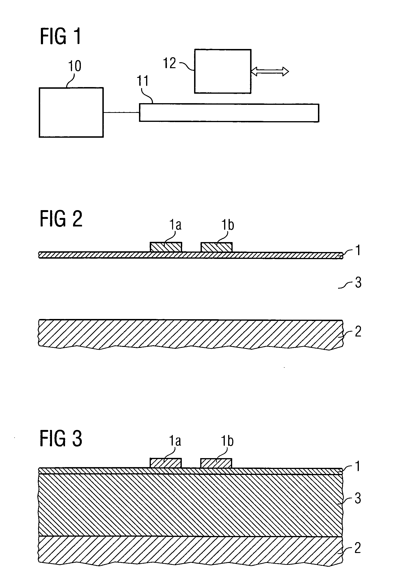
[0058] In FIG. 1 a device according to the invention is illustrated as an example. A transmitter 10 feeds electrical signals into the conductor arrangement 11. The receiver 12 is movably disposed opposite to the conductor arrangement 11 and the transmitter 10 connected thereto. The relative movement occurs along given tracks. Tracks of this kind may be linear or also circular, for example. The conductor arrangement 11 is disposed along at least one of these tracks of movement, so that at each point of the movement from which signals are to be transmitted there is only a short distance between the conductor arrangement 11 and the receiver 12. Typically the distances are within a range of 0.1 mm to about 10 mm. Direct contact at a distance of 0 is possible. This is a case of transmission via electrical contact. In order to maintain a long service life of the contact system here, it is necessary for the surfaces to be of special design. However, in a normal case the transmission is des...


PUM


Abstract

A device for signal transmission between units that are movable along given tracks comprises at least one transmitter for generating electrical signals, at least one conductor arrangement for conducting the electrical signals along a track of movement, and at least one receiver for coupling out electrical signals from a conductor arrangement. At least one conductor arrangement comprises at least one conductor structure for conducting electrical signals, an electric reference surface assigned thereto, and at least one dielectric between the conductor structure and the reference surface. A dielectric of the kind used has a high homogeneity, or a high symmetry with respect to the electrical center of the longitudinal axis of the conductor structure, or both.

Description

CROSS-REFERENCE TO RELATED APPLICATIONS [0001] This application is a continuation of pending International Application No. PCT / DE03 / 00455 filed on Feb. 14, 2003, which designates the United States and claims priority from pending German Application No. 102 06 160.2 filed on Feb. 14, 2002.FIELD OF THE INVENTION [0002] This invention relates to a device for transmitting electrical signals or energy between units movable relative to each other. [0003] For the sake of overall clearness, this document makes no distinction between transmission between units that are movable relative to each other, and transmission between a fixed unit and units movable relative thereto, because this is merely a question of positional reference and does not affect the manner of operation of the invention. In the same way, no detailed distinction is made between a transmission of signals and of energy, because here the mechanisms of operation are the same. DESCRIPTION OF THE PRIOR ART [0004] With linearly m...

Claims


Application Information

Patent Timeline
IPC IPC(8): H01Q1/38H01Q13/20
CPCH01Q13/206H01Q1/38
Inventor SCHILLING, HARRYLOHR, GEORG
Owner MICROSOFT CROPORATION
Why Eureka
Try Eureka