Video output device and method

a video output device and video technology, applied in the field of video output devices and methods, can solve the problems of increasing the cost of the device and the high cost of the display, and achieve the effect of easy production, easy and reliable achievement, and waste of process

Inactive Publication Date: 2005-02-24
ALPINE ELECTRONICS INC
View PDF7 Cites 16 Cited by
  • Summary
  • Abstract
  • Description
  • Claims
  • Application Information

AI Technical Summary

Benefits of technology

[0019] Preferably, the lighting unit includes a projection light source capable of changing the RGB ratio in accordance with the displayed video. Accordingly, lighting modes that fit the contents of the video can be easily produced.
[0020] Preferably, partitions forming a space containing the display unit are disposed around the display unit, and the lighting units emit light to the partitions. Using the partitions, such as a wall surface, a floor surface, and a ceiling surface, allows the lighting units to emit light without the need for special screens.
[0021] Preferably, an auxiliary screen is disposed in an area including the lighting zone of the lighting unit in the periphery of the display unit, and the lighting unit emits light to the auxiliary screen. By using the auxiliary screen, intended color and brightness by the lighting units can be easily and reliably achieved.
[0022] Preferably, the lighting control unit enables the lighting of the lighting unit when the brightness of the displayed video at a predetermined time is greater than or equal to a predetermined value. Since an observer does not perceive or does not sense the effect of lighting under a certain intensity, the lighting may be carried out only for bright scenes, not for such dark scenes. Thus, a wasted process and wasted power consumption can be reduced.
[0023] According to the present invention, a method for producing video includes; generating a video signal corresponding to displayed video; displaying the video based on the video signal with a display unit; controlling a lighting mode based on the content of the displayed video in synchronization with the display timing of the video to cause a lighting unit to be driven. By disposing the lighting units in the vicinity of the display unit and controlling the lighting modes in synchronization with the content of the video displayed on the display unit, video images having the same sense of presence provided by enlarging a screen of the display unit can be achieved. Additionally, the effective video display area of the display unit can be reduced and, therefore, the cost is reduced.
[0024] Preferably, the display unit has a display screen disposed within the normal viewing angle range of an observer of the displayed video, and the lighting zone of the lighting unit is disposed outside the normal viewing angle range and within the maximum viewing angle range of the observer. By replacing the actual image in the unrecognizable zones with lighting from the lighting units, displayed video has a strong visual effect which is the same as that of a bigger screen including the lighting zones. Additionally, the observer cannot even perceive color and brightness outside the maximum viewing angle range. Therefore, eliminating lighting of such zones limits the lighting zone required for increasing a sense of presence, thus reducing the power consumption and size of a facility.

Problems solved by technology

Unfortunately, although the multi-screen display disclosed in the above-described publication can provide a big screen with a sense of presence by using a plurality of projectors, the multi-screen display requires a plurality of projectors to display one scene of video and also assignment of each part of the scene to the corresponding projector.
This process is disadvantageously complicated, thereby increasing the cost of the device.
However, these displays are quite expensive.

Method used


Image

  • Video output device and method
  • Video output device and method
  • Video output device and method

Examples


Embodiment Construction

[0033] A video output device according to an embodiment of the present invention will now be described in detail with reference to the accompanying drawings.

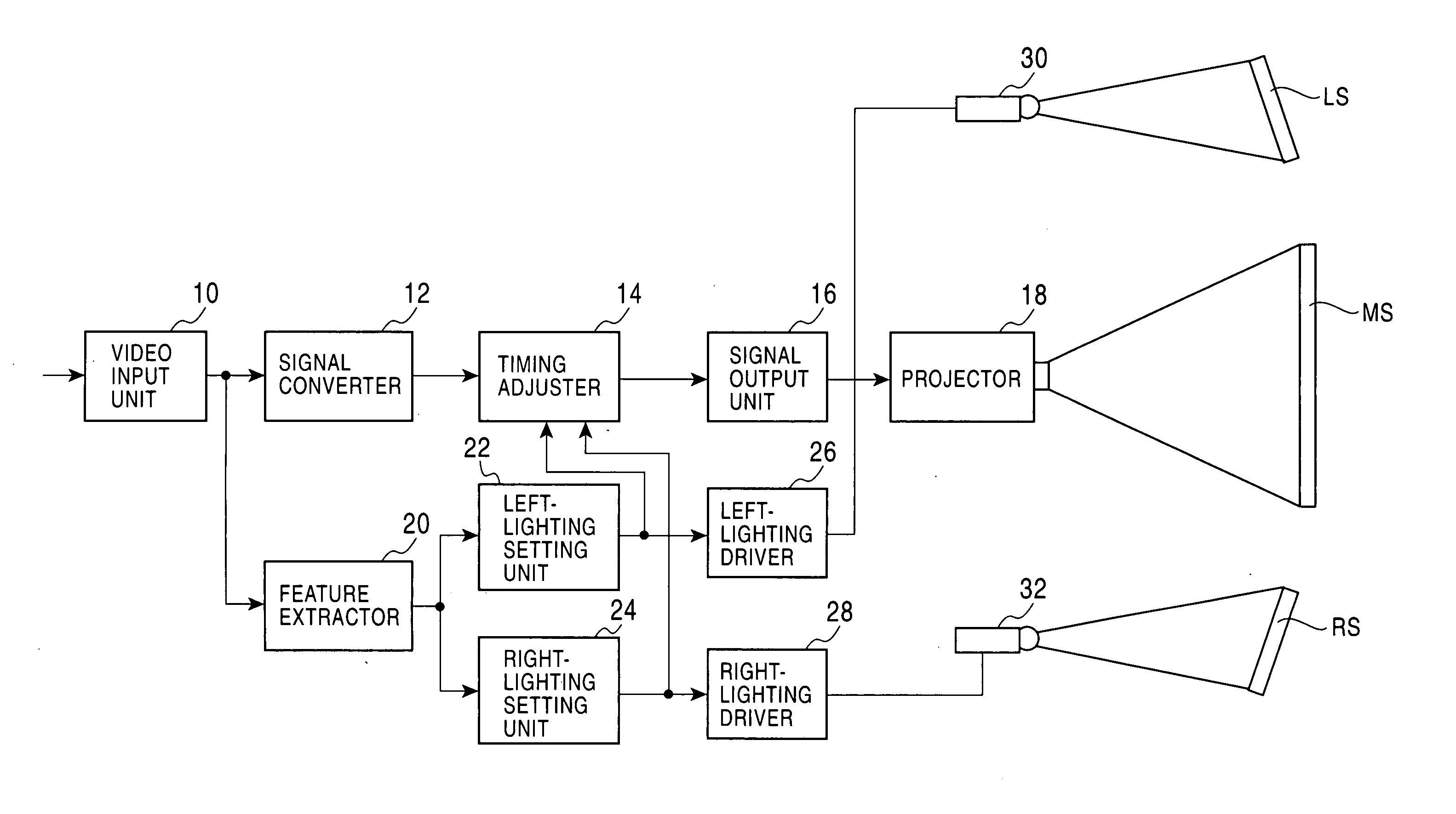
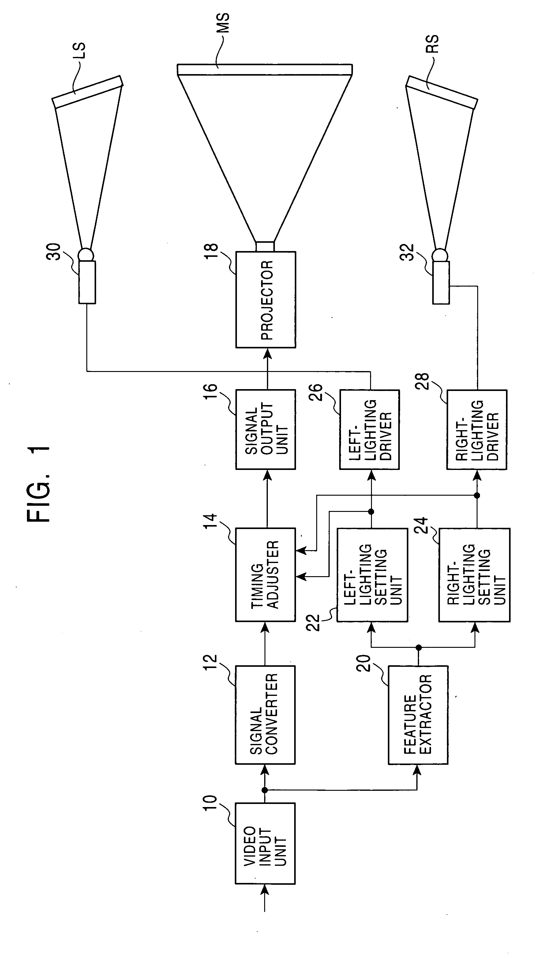
[0034]FIG. 1 is a block diagram of a video output device according to the embodiment. As shown in FIG. 1, the video output device according to the embodiment includes a video input unit 10, a signal converter 12, a timing adjuster 14, a signal output unit 16, a projector 18, a feature extractor 20, a left-lighting setting unit 22, a right-lighting setting unit 24, a left-lighting driver 26, a right-lighting driver 28, a left lighting unit 30, and a right lighting unit 32. In front of the projector 18, a main screen MS is disposed. In front of the left lighting unit 30 and the right lighting unit 32, a left screen LS and a right screen RS are disposed, respectively.

[0035] The video input unit 10 adjusts a level of video signal received from another external device, and then delivers the adjusted video signal to both the signal ...


PUM


Abstract

A video output device includes a signal converter for generating a video signal corresponding to displayed video; a projector and a main screen for displaying the video based on the video signal output from the signal converter; left and right lighting units, a left screen, and a right screen disposed in the vicinity of the main screen; and a feature extractor, a left-lighting setting unit, and a right-lighting setting unit for controlling lighting modes of the left and right lighting units based on the content of the displayed video in synchronization with the display timing of the video.

Description

BACKGROUND OF THE INVENTION [0001] 1. Field of the Invention [0002] The present invention relates to a video output device and a method for displaying video with a projector. [0003] 2. Description of the Related Art [0004] Multi-screen displays that can provide a super-high-resolution big screen consisting of multiple screens providing a sense of presence are known (refer to, for example, Japanese Unexamined Patent Application Publication No. 2002-107831, in particular, pages 4 to 7 and FIGS. 1 to 13). In such multi-screen displays, four projectors are arranged closely by placing two projectors side by side in the vertical direction and the horizontal direction, in the vicinity of the center of the screen at a distance from its back side. Thus, by disposing a plurality of projectors at the center of a screen on its back side, a big screen that provides a sense of presence can be achieved without increasing the directivity of the screen. [0005] Unfortunately, although the multi-scree...

Claims


Application Information

Patent Timeline
Patent Type & Authority Applications(United States)
IPC IPC(8): G03B21/00B60R11/00B60R11/02F21S2/00F21S10/00F21V14/00G09F9/00G09G3/20H04N5/74H05B37/02
CPCB60R11/02B60R11/0211H04N5/74B60R2011/0085B60R2011/0028
Inventor SATO, TAKESHI
Owner ALPINE ELECTRONICS INC
Why Eureka
Try Eureka