

Method of and apparatus for cracking connecting rod
Patent Information
- Authority / Receiving Office
- US · United States
- Patent Type
- Applications(United States)
- Current Assignee / Owner
- HONDA MOTOR CO LTD
- Publication Date
- 2005-03-03
- Estimated Expiration
- Not applicable · inactive patent
Smart Images
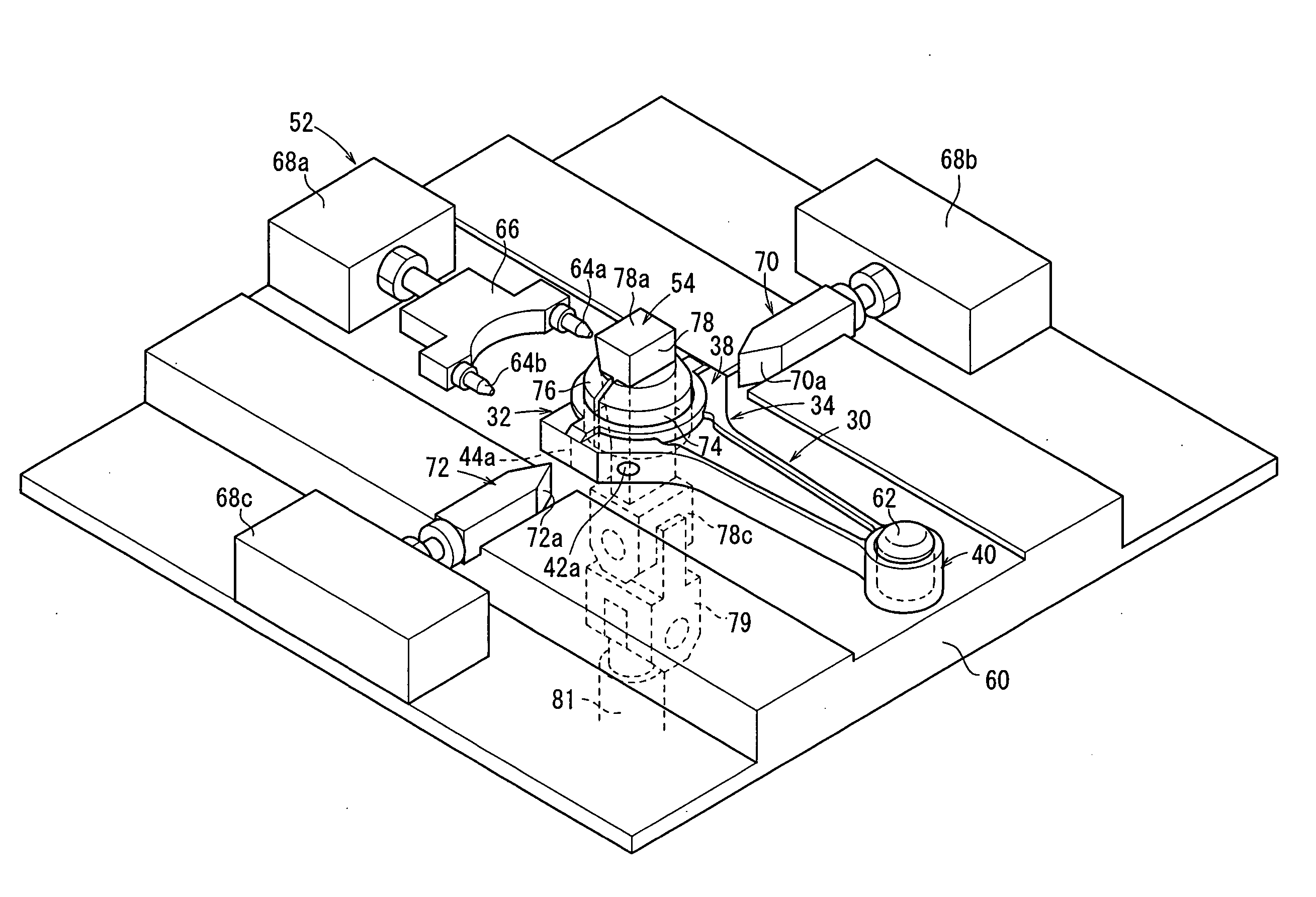
Figure 1 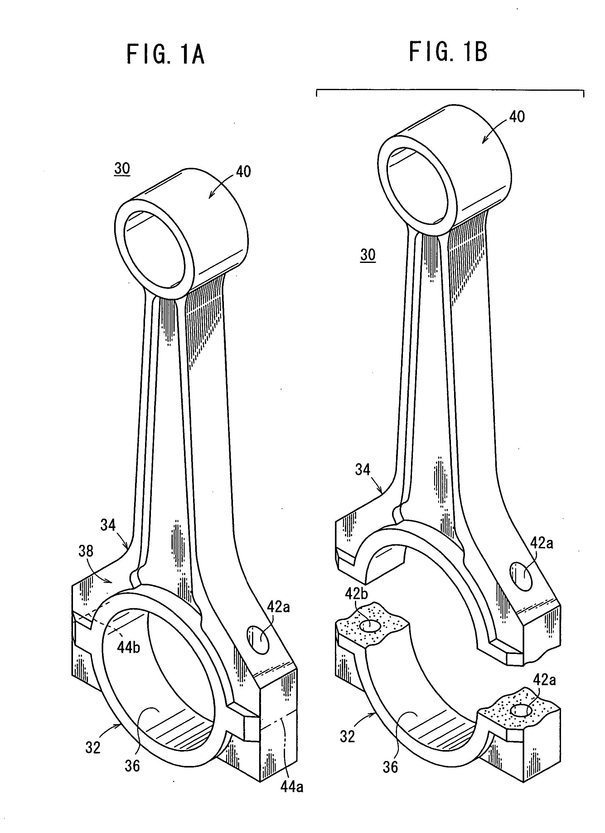
Figure 2 
Figure 3
Abstract
Description
BACKGROUND OF THE INVENTION
[0001] 1. Field of the Invention
[0002] The present invention relates to a method of and an apparatus for cracking a one-piece connecting rod, which serves as an engine component for vehicles and which has a larger end and a smaller end, to fracture the larger end into a cap and a rod.
[0003] 2. Description of the Related Art
[0004] Heretofore, connecting rods interconnecting piston pins and crank pins have widely been used in vehicular engines. Each of the connecting rods has a larger end coupled to the crankpin and a smaller end coupled to the piston pin. For manufacturing a connecting rod, it is generally customary to produce a one-piece connecting rod having a larger and a smaller end and thereafter to fracture the larger end into a cap and a rod.
[0005] One conventional process of fracturing a connecting rod will be described below.
[0006] As shown in FIG. 17 of the accompanying drawings, a one-piece connecting rod 5 includes a shank 1 having a small...