Hydraulic control arrangement for a mobile work machine

a technology of hydraulic control and mobile work machine, which is applied in the direction of fluid couplings, servomotors, instruments, etc., can solve the problems of increasing non-synchron movement, oscillation or shaking of operating tools, and not always smooth and without jerks

Inactive Publication Date: 2005-03-03
DEERE & CO
View PDF8 Cites 23 Cited by
  • Summary
  • Abstract
  • Description
  • Claims
  • Application Information

AI Technical Summary

Benefits of technology

[0008] According to the present invention, there is provided an improved safety arrangement for use in the hydraulic circuitry of a lifting device.
[0009] An object of the invention is to provide such a hydraulic circuitry with a safety valve that reaches an open position automatically and independently of the pressure in the pressure chamber of a lifting cylinder when the operating tool is lowered and / or when a float operating mode is selected by an operator. Thereby, the pressure in the pressure chamber, which is emptied during the lowering of the operating tool, is not considered, so that any pressure differences in the pressure chambers of two cylinders moved synchronously cannot become detrimental. Furthermore the opening of the safety valve is performed without any effect from environmental conditions, such as the viscosity, the temperature and the rate of flow of the hydraulic fluid. The open safety valve does not impair the hydraulic operation of the lifting gear by undesirable flow resistances, since in its open position the safety valve can be provided with a sufficiently large flow opening.
[0010] As an alternative, or in addition, it s proposed that the safety valve open automatically if the operator has selected a float operating move. Then the operating tool, as a rule, is lowered and lies upon the ground or on another support surface, although it would be conceivable to activate this mode of operation for special applications even with a raised operating tool. Thereby the pressure in the pressure chamber of the hydraulic cylinder is preferably not considered in the control of the safety valve, although embodiments would also be conceivable in which it is considered. An advantage lies in the fact that in this way a floating operating move becomes possible, for example, for surface copying in which the pressure chamber is loaded for the raising of the operating tool and it as well as a second chamber of the double-acting cylinder are connected to each other over the directional control valve that is brought into a float position and the safety valve now opened. As a rule, they are also connected to the tank.
[0012] In another embodiment, the safety valve is controlled electromagnetically or hydraulically on the basis of an input from the operator. The operator input can be detected directly, for example, by a switch contact at an operator input arrangement, or indirectly in which the position of an element influenced by the operator input arrangement is detected, for example, the directional control valve. In this embodiment, single-acting or double-acting cylinders can be applied. Combinations of a hydraulic and electromagnetic detection of the operating mode are also possible as is a control arrangement of the safety valve based on these. In this way, the lifting and holding operating mode can be detected hydraulically and the lowering and float operating mode can be detected on the basis of operator input.
[0014] an obvious solution is to equip the pressure chamber of each of these cylinders, to which pressure is applied during the lifting of the operating tool, with a safety valve according to the invention. alternatively, only a single safety valve is applied, that is connected with the pressure chambers of the cylinders. To avoid possible hose failures and the safety risks associated with these, this connection is preferably performed by mechanically rigid line elements, particularly tubes.

Problems solved by technology

With these safety valves, the disadvantage is seen in that the lowering movement is not always performed smoothly and without jerks, if two or more cylinders are provided that together perform a single movement.
The safety valves associated with the individual cylinders frequently have different response sensitivities so that they do not open synchronously upon the lowering of the operating tool, which has the result that the cylinders are not lowered synchronously and the operating tool oscillates or shakes during the lowering.
Moreover, thereby differing flow velocities in turn result in differing pressure differences at the safety valves that further increase the non-synchronous movement.
An operation in the floating move, in which the chambers of a double-acting hydraulic cylinder are connected to each other so as to conduct fluid, is not possible with the known safety valves, since they are always blocked when the cylinder is not being repositioned.
For this purpose, DE 100 06 908 A provides a second valve which, however, increases the cost and the risk of a line failure.

Method used


Image

  • Hydraulic control arrangement for a mobile work machine
  • Hydraulic control arrangement for a mobile work machine
  • Hydraulic control arrangement for a mobile work machine

Examples


fourth embodiment

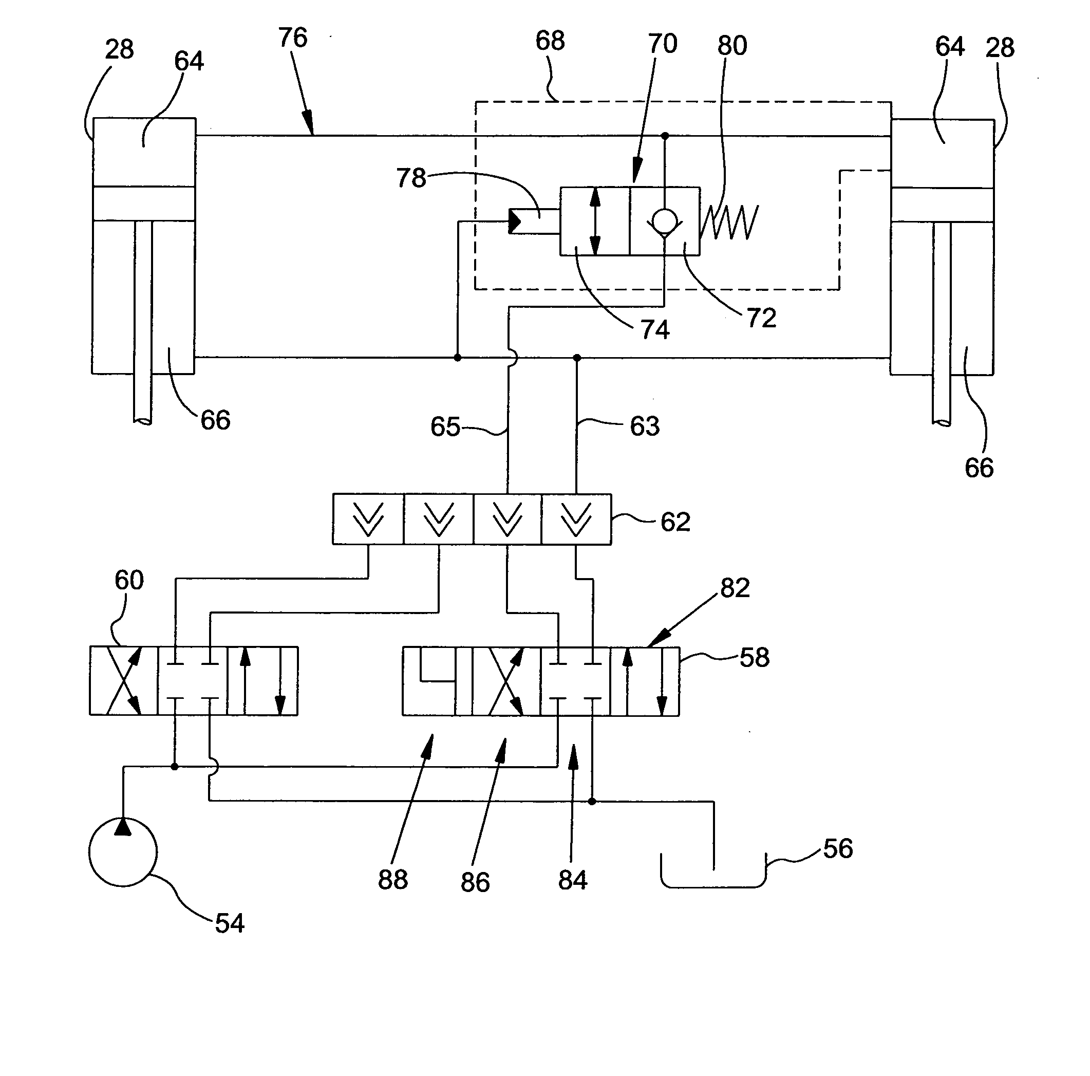
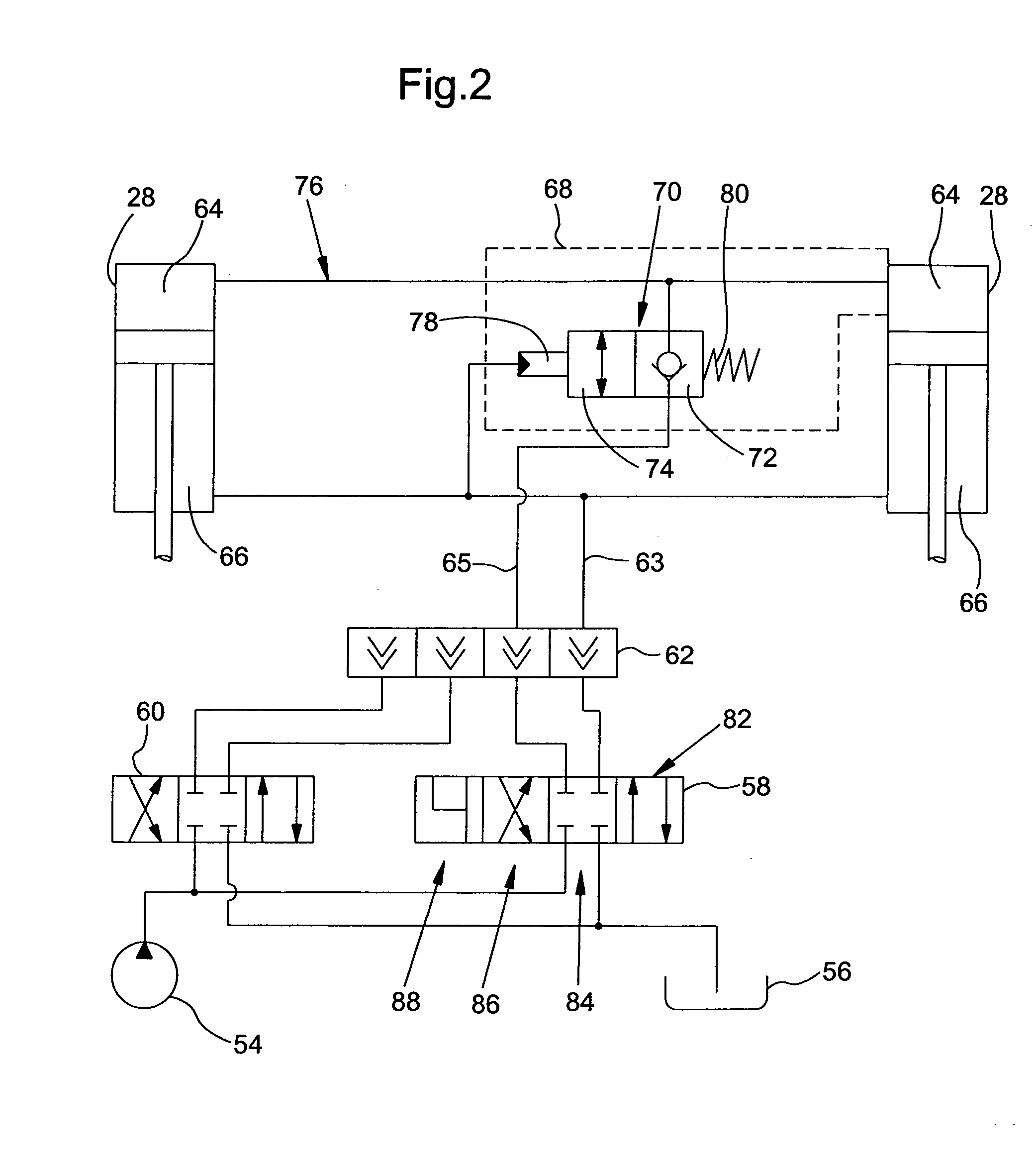
[0039]FIG. 5 shows a control arrangement according to the invention whose configuration and function corresponds generally to that of FIG. 4. Elements corresponding to the embodiments described previously are identified with the same part number call-outs. The difference from the configuration according to FIG. 4 consists of the fact that only a single safety valve 70 is provided, that is fastened directly to one of the cylinders 28 and whose outlet is connected to the other cylinder 28 by a rigid line.

[0040] The FIGS. 6a through 8 show configurations of arrangements for the control of the electromagnetic actuator 90, that can be used in the embodiments according to FIGS. 4 and 5. In the embodiment according to FIG. 6a, an operating element 92 is provided with a series of cables 96 that are provided for the electromagnetic control of the direction control valve 58, the operating element is in the form of a so-called joystick, that is used for the control of the direction control val...

fifth embodiment

[0043] Finally, FIG. 9 shows a control arrangement that corresponds generally in configuration and function to the control arrangement of the embodiment of FIG. 4. Elements corresponding to the embodiment according to FIG. 4 are identified with the same part number call-outs. However, the control of the safety valves 70 is performed by a hybrid hydraulic / electromagnetic control arrangement. There the hose 63, that is connected with the rod end chambers 66, is connected with a pressure switch 112. The pressure switch 112 contains a switch contact 114 that switches on or off at a pressure in the hose 63 which can be adjusted by means of an adjustable spring 116. Analogously to the switching arrangement of FIG. 8, the switch contacts 114 are connected over a fuse 106, the coils of a relay 108 and a spark extinguishing diode 110 with a battery 104, which as a rule, is also the battery of the tractor. The actuator 90 of the safety valve 70 is controlled by the switch contacts of the rela...


PUM


Abstract

A hydraulic control arrangement for a mobile work machine includes at least one hydraulic cylinder by means of which an operating tool can be moved. A direction control valve is provided for controlling the path of pressurized fluid between a pressure chamber of the cylinder, a pump, and a tank, as well as a safety valve inserted between the directional control valve and the pressure chamber of the cylinder to which pressure is applied during the lifting of the operating tool. The safety valve opens automatically when presssure is applied to the cylinder and is closed when no pressure is applied to the cylinder. The safety valve further operates so that it opens, automatically and independently of the pressure in the pressure chamber, during the lowering of the operating tool and / or during a float operating mode, selected by an operator.

Description

FIELD OF THE INVENTION [0001] The invention concerns a hydraulic control arrangement for a mobile work machine with at least one hydraulic cylinder, by means of which an operating tool can be moved, a directional control valve for the control of the path of the pressurized medium between the pressure chamber of the cylinder, a source of pressurized medium and a tank, as well as a safety valve inserted between the directional control valve and the pressure chamber of the cylinder to which pressure is applied during the raising of the operating tool, which opens automatically when pressure is applied to the cylinder and is blocked when no pressure is applied to the cylinder. BACKGROUND OF THE INVENTION [0002] Lifting gear arrangements, for example, front loaders, are attached to machines and used for lifting and transporting loads. They are provided with hydraulic cylinders for lifting the loads and, as a rule, also for pivoting the load, and are supplied with pressurized hydraulic fl...

Claims


Application Information

Patent Timeline
Patent Type & Authority Applications(United States)
IPC IPC(8): F15B11/00F15B20/00
CPCF15B11/003F15B2211/7128F15B2211/20538F15B2211/30505F15B2211/3051F15B2211/30525F15B2211/3111F15B2211/3127F15B2211/31588F15B2211/40515F15B2211/413F15B2211/41545F15B2211/426F15B2211/428F15B2211/46F15B20/005
Inventor BERTHOD, EMMANUELOSTERMANN, PHILIPPE
Owner DEERE & CO
Why Eureka
Try Eureka