Brake master cylinder and manufacturing method therefor

a technology of brake master cylinder and manufacturing method, which is applied in the direction of rotary clutches, braking systems, fluid couplings, etc., can solve the problems of increasing the number of components therefor, the inability to arrange the resin-made sleeves, and the complexity of construction, so as to reduce the number of components and simplify construction.

Inactive Publication Date: 2005-03-03
ADVICS CO LTD
View PDF7 Cites 21 Cited by
  • Summary
  • Abstract
  • Description
  • Claims
  • Application Information

AI Technical Summary

Benefits of technology

[0007] Accordingly, it is a primary object of the present invention to provide an improved brake master cylinder capable of having a sleeve inserted into a one-piece cylinder body so that the master cylinder can be simplified in construction and decreased in number of the components therefor.

Problems solved by technology

However, because of taking a cylindrical shape, the resin-made sleeve cannot be arranged between the first cup seal, which is kept in contact with the first piston guide fit in the rear body, and the fluid-tight seal element unless the cylinder body is divided into the front body and the rear body.
This disadvantageously increases the number of the components therefor and makes the construction complicated.

Method used


Image

  • Brake master cylinder and manufacturing method therefor
  • Brake master cylinder and manufacturing method therefor
  • Brake master cylinder and manufacturing method therefor

Examples


Embodiment Construction

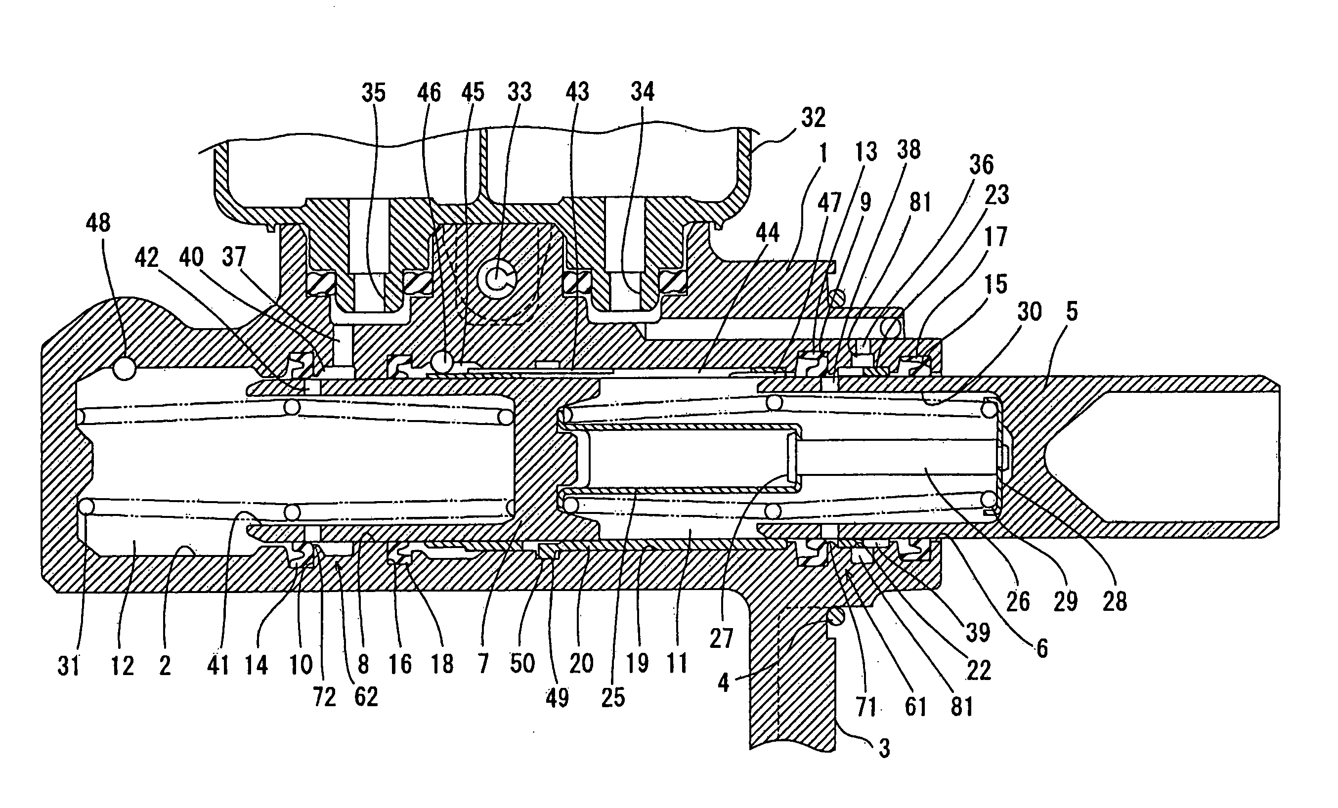
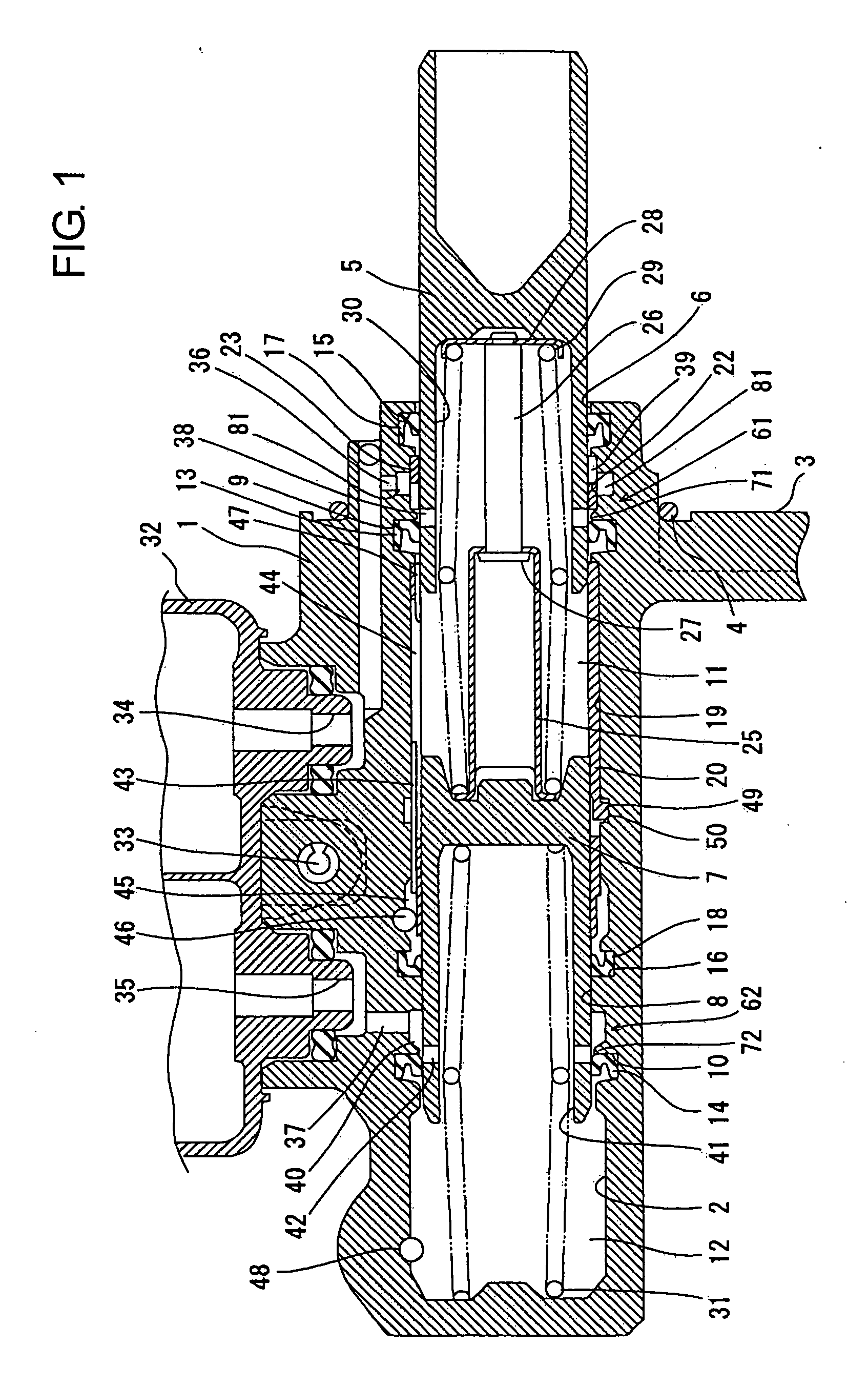
[0016] A master cylinder according to an embodiment of the present invention will be described hereinafter with reference to the accompanying drawings. Referring now to FIG. 1, a metal-made cylinder body 1 is shown formed with a cylinder 2 having a bottom wall at its front end and opening at its rear end. At the rear end portion of the cylinder body 1, there is formed a booster attaching surface 3, to which a booster of a vacuum booster device (not shown) is secured through an O-ring 4. At the rear end portion of the cylinder 2 and beside a first cup seal 13, there is formed a first piston guide portion 61, into which a metal-made first piston 5 is inserted with a play. At the intermediate portion of the cylinder 2 and beside a second cup seal 14, there is formed a second piston guide portion 62, into which a metal-made second piston 7 is inserted with a play. The front end portions of the first and second piston guide portions 61, 62 are formed with annular grooves 9, 10, in which ...


PUM


Abstract

In a brake master cylinder, when a first piston is pushed forward, first and second fluid chambers of a cylinder which are partitioned respectively by first and second cup seals supply brake fluids therefrom to first and second brake systems. Even when slightly inclined upon receiving a pushing force, the first piston is slidably guided along a first sleeve which is softer than the first piston, without coming into contact with the cylinder body. Since the first piston is not abrasively damaged, it does not occur that the first cup seal is injured at a slide guide portion thereof. Further, each of the first sleeve and a second sleeve is separated at one portion in the circumferential direction throughout the whole length thereof, so that by being inserted from an opening end of the cylinder, the sleeves can be fit respectively in sleeve recesses which are annually formed respectively at a first piston guide portion of a cylinder internal surface, which is bored in a cylinder body as one piece, and another portion between first and second piston guide portions of the cylinder internal surface.

Description

INCORPORATION BY REFERENCE [0001] This application is based on and claims priority under 35 U.S.C. 119 with respect to Japanese Application No. 2003-310977 filed on Sep. 3, 2003, the entire content of which is incorporated herein by reference. BACKGROUND OF THE INVENTION [0002] 1. Field of the Invention [0003] The present invention relates to a brake master cylinder for use in a brake system for a vehicle and a manufacturing method therefor. [0004] 2. Discussion of the Related Art [0005] Heretofore, there has been known a brake master cylinder described in U.S. Pat. No. 6,381,959 B1 (equivalent of Japanese unexamined, published patent application No. 2001-138893. In the known brake master cylinder, a metal-made cylinder body is constituted by screwing a rear body into a rear end of an internal bore formed in a front body. A metal-made first piston is slidably inserted into a resin-made first piston guide which is fit in a rear end portion of an internal bore formed in the rear body,...

Claims


Application Information

Patent Timeline
Patent Type & Authority Applications(United States)
IPC IPC(8): B60T11/16B60T11/20B60T11/236
CPCB60T11/236B60T11/16
Inventor TSUBOUCHI, KAORUMITA, KATSUHIRO
Owner ADVICS CO LTD
Why Eureka
Try Eureka