
Tubular element for an air-conditioning circuit

Inactive Publication Date: 2005-03-03
HUTCHINSON SA
View PDF16 Cites 4 Cited by
  • Summary
  • Abstract
  • Description
  • Claims
  • Application Information

AI Technical Summary

Benefits of technology

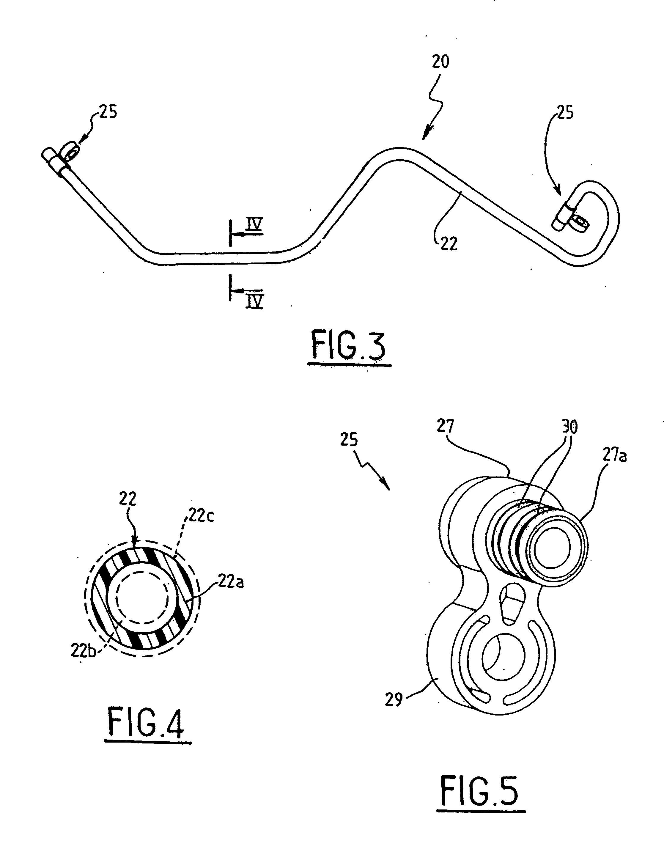
[0007] Advantageously, the tubular element is made of a thermoplastic material such as a polyamide, in particular a polyamide 6-6, and presents a certain amount of flexibility.
[0010] A one-piece and single-layer tubular element of the invention presents numerous advantages compared with a prior art solution where the tubular element is constituted in particular by at least one rigid tubular element that needs to be connected to at least one flexible tubular element.
[0011] Amongst the advantages, mention can be made in particular of the elimination of crimped connections between the rigid and flexible tubular elements, where such connections can be sources of refrigerant fluid leakage, a weight saving that can be estimated as being about 50%, elimination of flow constrictions between the rigid and flexible tubular elements, an increase in compactness, the elimination of any potential pollution added during the stage when the connections are made, and the possibility of optimizing the inside diameter and the thickness of these tubular elements, where such optimization is not possible with prior art high-pressure hoses for economic reasons, since purchasing volumes are too small for it to be possible to obtain rigid tubular elements from suppliers having as many different sizes as might be desirable.

Problems solved by technology

That type of connection can lead to refrigerant fluid leakage, locally increases the size of the high-pressure hose, and leads to a flow constriction for the refrigerant fluid.

Method used


Image

  • Tubular element for an air-conditioning circuit
  • Tubular element for an air-conditioning circuit
  • Tubular element for an air-conditioning circuit

Examples


Embodiment Construction

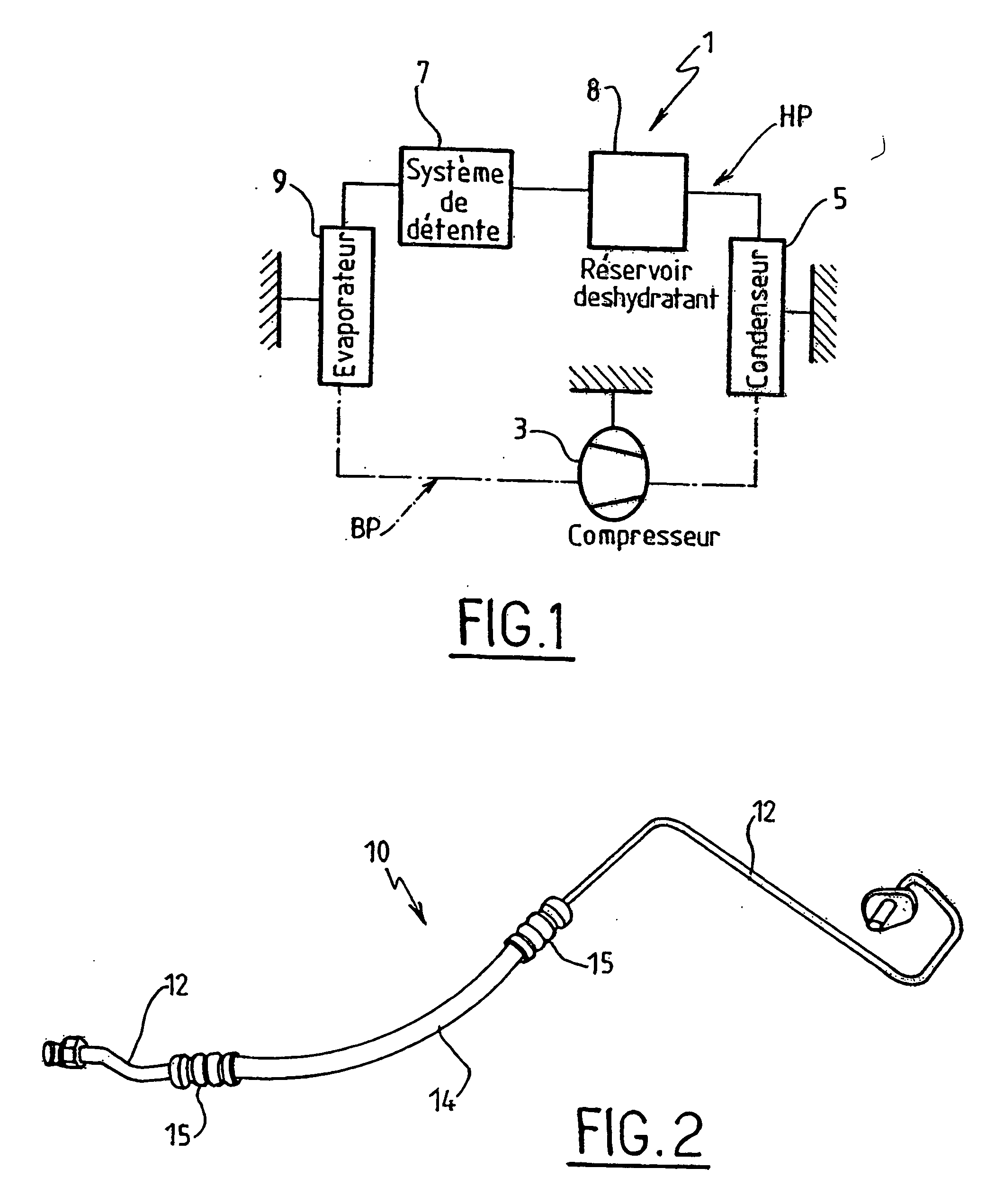
[0019]FIG. 1 is a diagram showing an embodiment of an air-conditioning circuit 1 for a motor vehicle, for example. This air-conditioning circuit 1 is a closed circuit comprising a compressor 3 which is driven by the engine shaft of the vehicle, a condenser 5, an expander system 7, a receiver / dryer 8, and an evaporator 9. In the air-conditioning circuit, there is a low-pressure portion LP, and a high-pressure portion HP situated between the compressor 3 and the expansion system 7 in which the refrigerant fluid, in particular R134A, is at a temperature of abut 100° C. and at a pressure of about 20 bars.

[0020] The various elements of this air-conditioning circuit 1 are interconnected by hoses, each of which is constituted by a flexible or rigid tubular element having connection means at both ends, or by an appropriate combination of flexible and rigid elements.

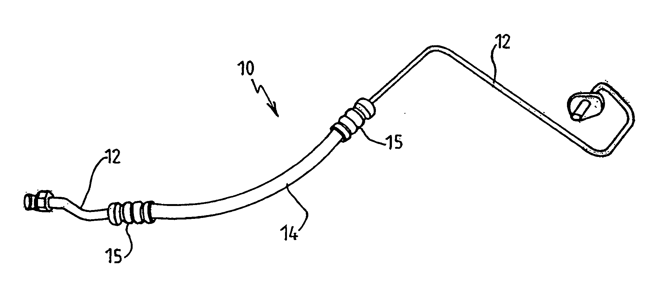
[0021]FIG. 2 shows a prior art hose 10 which is mounted in the high-pressure portion HP of the air-conditioning circuit, this...


PUM


Abstract

A tubular element for transporting a refrigerant fluid between two components of an air-conditioning circuit, said element being a one-piece tube, wherein the tube is a single-layer tube of plastics or thermoplastic material.

Description

[0001] The invention relates to a tubular element for an air-conditioning circuit for a motor vehicle, for example. BACKGROUND OF THE INVENTION [0002] An air-conditioning circuit is a closed circuit comprising a plurality of elements, in particular a compressor, a condenser, an accumulator, an expander system, and an evaporator, with a refrigerant fluid that circulates around the circuit. All of the elements are interconnected by hoses constituted by flexible and / or rigid tubular elements, and each presenting a fastener element towards each of its ends, and means for leaktight coupling. The elements of an air-conditioning circuit are distributed inside the vehicle engine compartment, it being understood that the compressor is driven by the vehicle engine shaft, whereas the other elements are attached to the bodywork of the vehicle. An air-conditioning circuit of that type can be subdivided into a low-pressure portion and a high-pressure portion, comprising in particular the condense...

Claims


Application Information

Patent Timeline
IPC IPC(8): B60H1/00F16L11/12F25B41/00
CPCB60H1/00571F16L9/127F25B41/003F16L11/122F16L11/04F25B41/40
Inventor TOURTE, MARCLEMOINE, JEAN-PHILIPPE
Owner HUTCHINSON SA
Learn More