Method of progressive hydro-forming of tubular members

a tubular member and progressive technology, applied in the field of tubular member forming, can solve the problem that the above-described hydro-forming process cannot be used for the fuel filler neck and manifold, and achieve the effects of reducing cost and mass, eliminating brazing seams, and improving part quality

Inactive Publication Date: 2005-03-03
GM GLOBAL TECH OPERATIONS LLC
View PDF23 Cites 10 Cited by
  • Summary
  • Abstract
  • Description
  • Claims
  • Application Information

AI Technical Summary

Benefits of technology

[0008] One advantage of the present invention is that a method of progressive hydro-forming of a tubular member is provided for a vehicle component, such as a fuel filler neck and manifold. Another advantage of the present invention is that the method allows the use of smaller diameter tubes, resulting in less cost and mass. Yet another advantage of the present invention is that the method improves part quality, eliminating brazing seams and allowing improved part repeatability. Still another advantage of the present invention is that the method reduces tooling expense. A further advantage of the present invention is that the method can produce an integral one-piece part, thereby eliminating several pieces of deep drawn stampings that are brazed together.
[0009] Other objects, features, and advantages of the present invention will be readily appreciated, as the same becomes better understood, after reading the subsequent description taken in conjunction with the accompanying drawings.

Problems solved by technology

However, the above-described hydro-forming process could not be used for the fuel filler neck and manifold because of the expansion requirements of the manifold sections.

Method used


Image

  • Method of progressive hydro-forming of tubular members
  • Method of progressive hydro-forming of tubular members
  • Method of progressive hydro-forming of tubular members

Examples


Embodiment Construction

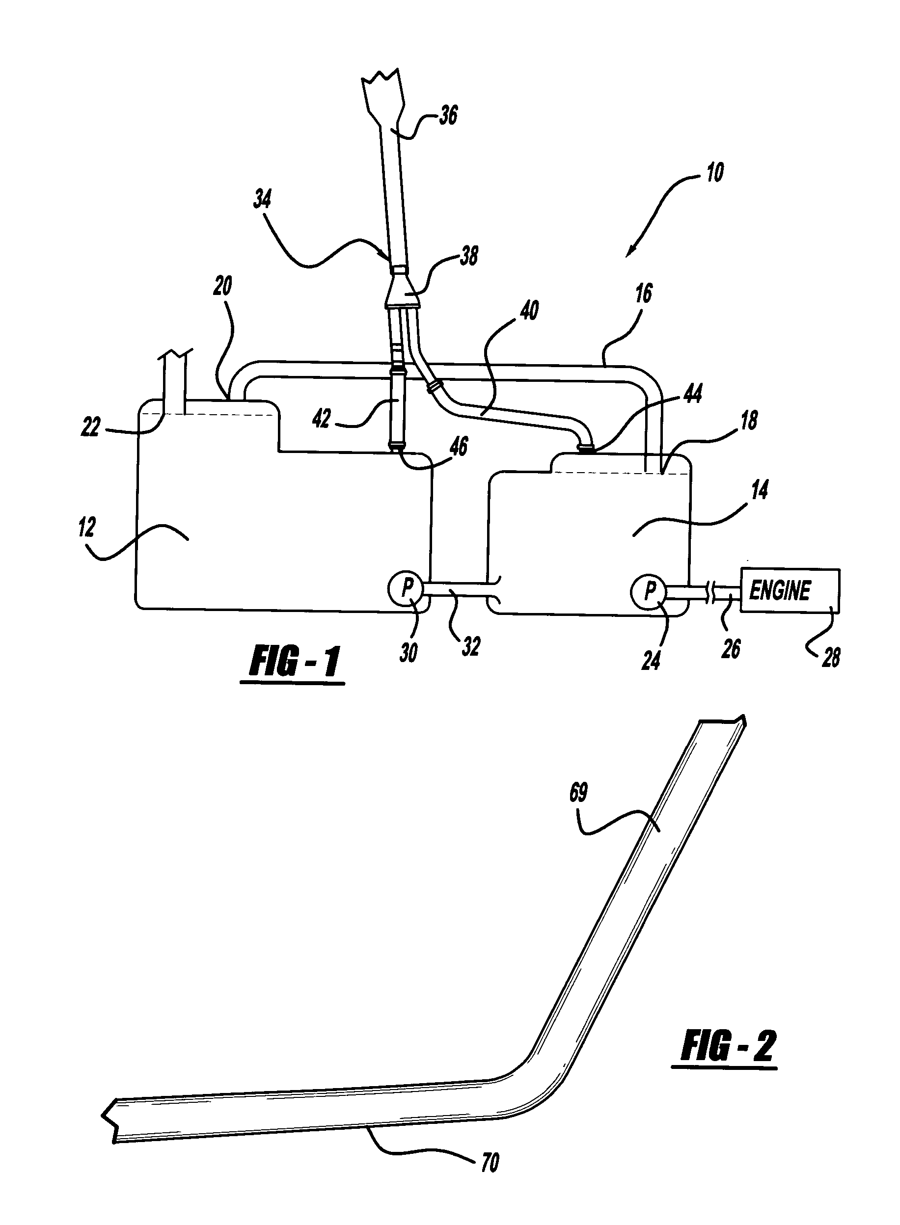
[0016] Referring to the drawings and in particular FIG. 1, one embodiment of a dual fuel tank simultaneous fill system 10 is generally shown for a vehicle (not shown). The fill system 10 includes a first fuel tank 12 and a second fuel tank 14. The fill system 10 also includes a vapor relief line 16 fluidly connected to the first fuel tank 12 and the second fuel tank 14 from a first tank vent / overflow outlet 18 on the first fuel tank 12 to a second tank overflow inlet 20 on the second fuel tank 14. The fill system 10 includes a vapor relief outlet 22 connected to the second fuel tank 14 and vented to atmosphere.

[0017] The fill system 10 further includes a first pump 24 that draws fuel only from the first fuel tank 10 and delivers it via a line 26 to an engine 28 of the vehicle. The fill system 10 includes a second pump 30 that transfers fuel via a line 32 from the second fuel tank 14 to the first fuel tank 12. It should be appreciated that, as fuel is drawn from the first fuel tank ...


PUM

PropertyMeasurementUnit
hydraulic pressureaaaaaaaaaa
circular cross-sectional shapeaaaaaaaaaa
pressureaaaaaaaaaa

Abstract

A method of progressive hydro-forming of a tubular member includes the steps of positioning a tubular member between open die halves mating with one another to define a first tubular cavity portion in a first stage. The method also includes the steps of progressively closing the die halves and applying hydraulic pressure to expand and conform the tubular member to the first tubular cavity portion in the first stage. The method includes the steps of positioning the expanded tubular member in a second tubular cavity portion in a second stage and progressively closing the die halves to progressively deform the expanded tubular member within the second tubular cavity portion. The method includes the steps of applying hydraulic pressure to expand and conform the expanded tubular member to the second tubular cavity portion in the second stage.

Description

TECHNICAL FIELD [0001] The present invention relates generally to forming a shaped tubular member and, more particularly, to a method of progressive hydro-forming of tubular members for automotive components. BACKGROUND OF THE INVENTION [0002] It is known to form a cross-sectional profile of a tubular member by a hydro-forming process in which a fluid filled tubular blank is placed within a die and then the die is closed so that the tubular blank is formed within the die. Fluid pressure is then increased inside the tubular member to expand the blank outwardly against the die cavity to provide a tubular component having a die formed cross-sectional profile. The tubular component may also have different cross-sectional profiles along the length thereof. [0003] For an automotive component such as a fuel filler neck or manifold of a fuel fill system, the fuel filler neck and manifold are made with several pieces of deep drawn stampings and brazed together to form a leak-free tubular mem...

Claims


Application Information

Patent Timeline
Patent Type & Authority Applications(United States)
IPC IPC(8): B21D26/02
CPCB21D26/033
Inventor NI, CHI-MOUSTRZELECKI, EDWARD J.
Owner GM GLOBAL TECH OPERATIONS LLC
Why Eureka
Try Eureka