Multicylinder four-cycle combustion engine

a combustion engine and four-cylinder technology, applied in the direction of machines/engines, cylinders, casings, etc., can solve the problems of increasing the pumping loss, imposing limitations on the leading open end of the respective communication hole, and unable to secure a sufficient passage area for the communication hole under such limitations of vertical size, so as to achieve smooth flow and reduce the effect of piston pumping loss

Active Publication Date: 2005-03-03
KAWASAKI MOTORS LTD
View PDF0 Cites 15 Cited by
  • Summary
  • Abstract
  • Description
  • Claims
  • Application Information

AI Technical Summary

Benefits of technology

[0009] In view of the foregoing, the present invention is intended to provide a multicylinder four-cycle combustion engine of a type, in which communication holes effective to allow gases to smoothly flow from one cylinder bore to another can be formed easily and in which the piston pumping loss can advantageously be reduced.

Problems solved by technology

Those design requirements impose limitations on the size of the leading open end of the respective communication hole, particularly the size of the leading open end as measured in a direction conforming to the direction of reciprocating movement of the piston or a vertical direction.
Since each of the communication holes has a round section as discussed above, the size of the open end in the vertical direction for a given cross-sectional surface area (passage area) of the respective communication hole tends to be large, and accordingly, it is difficult to secure a sufficient passage area for the communication hole under the limitations on such vertical size.
Moreover, the presence of the burrs around the open end of the communication hole tends to impose a relatively large resistance to the flow of gases through the communication hole.
Partly because of the insufficient passage area for each communication hole and partly because of the relatively large resistance to the gas flow caused by the burrs, the gases would not flow smoothly therethrough, resulting in increase of the pumping loss.

Method used


Image

  • Multicylinder four-cycle combustion engine
  • Multicylinder four-cycle combustion engine
  • Multicylinder four-cycle combustion engine

Examples


Embodiment Construction

[0029] Hereinafter, the present invention will be described in detail in connection with a preferred embodiment thereof with reference to the accompanying drawings.

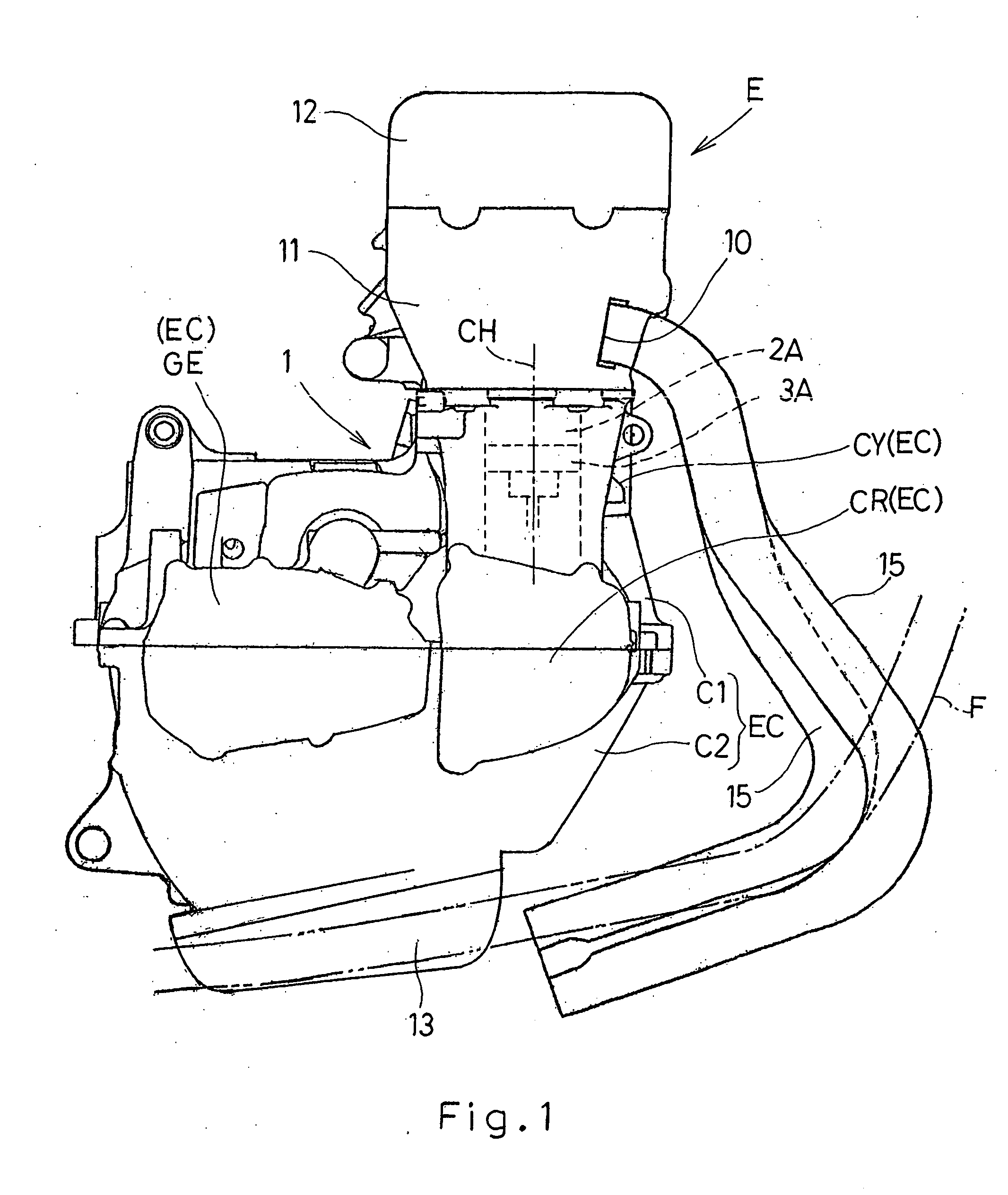
[0030] Referring first to FIG. 1, there is shown a side view of an essential portion of a multicylinder four-cycle internal combustion engine E for use in a motorcycle according to the present invention. The combustion engine is shown as fixedly mounted on a motorcycle frame structure F and is in the form of a four-cylinder, four-cycle internal combustion engine. The illustrated combustion engine E includes an engine body 1, which in turn includes an engine casing EC made up of a crankcase CR, a cylinder block CY and a gear case GE. The engine casing EC is of a two-piece construction including an upper casing component C1 and a lower casing component C2. The cylinder block CY, an upper half portion of the crankcase CR and an upper half portion of the gear case GE integrally are formed in the upper casing component C1 whi...


PUM


Abstract

There is provided a multicylinder four-cycle combustion engine, in which a communication hole is formed, to allow gases to flow smoothly form one cylinder to another so that the pumping loss occurring within the cylinders can be reduced. The combustion engine (E) includes an engine casing (EC) having defined therein a plurality of cylinders (2A to 2D), each having a cylinder bore (20A to 20D), and a crank chamber (30A to 30D) below the respective cylinder bore. A partition wall (21) separating the neighbor cylinder bores (20A, 20B; 20C, 20D) of the cylinders (2A to 2D) and the crank chambers (30A to 30D) from each other is formed with a communication hole (4). An open edge portion (4aa) of the uppermost edge (4a) thereof, which opens into the cylinder bore (20A to 20D) has a circumferentially intermediate major portion extending in a direction substantially perpendicular to the cylinder longitudinal axis (CH).

Description

BACKGROUND OF THE INVENTION [0001] 1. Field of the Invention [0002] The present invention generally relates to a multicylinder four-cycle combustion engine for use primarily in motorcycles and, more particularly, to the multicylinder four-cycle combustion engine of a kind in which the piston pumping loss can be reduced. [0003] 2. Description of the Prior Art [0004] In order to reduce the number of component parts of the multicylinder four-cycle combustion engine and, also, to reduce the number of manufacturing steps, it is well known that some of multicylinder four-cycle combustion engines currently used in motorcycles are of a structure in which a cylinder block and a generally upper half of a crankcase are formed integrally with each other. In the case of such multicylinder four-cycle combustion engine, crank chambers one for each cylinder are separated from each other by means of partition walls. Therefore, in order to alleviate the piston pumping loss which would result from as ...

Claims


Application Information

Patent Timeline
Patent Type & Authority Applications(United States)
IPC IPC(8): F02F7/00F02F1/00
CPCF02F7/0007
Inventor KAWAMOTO, YUICHITERAO, TOMOYUKIASANO, MATSUHIROMATSUDA, YOSHIHARU
Owner KAWASAKI MOTORS LTD
Why Eureka
Try Eureka