Planar heat pipe structure

a technology of heat pipe and planar heat pipe, which is applied in the direction of indirect heat exchangers, light and heating equipment, laminated elements, etc., can solve the problems of inability to properly enhance the heat dissipation efficiency, and inability to effectively dissipate the increasing heat generated by the higher operation speed. , to achieve the effect of improving the structure of the planar heat pip

Inactive Publication Date: 2005-03-03
PYROSWIFT HOLDING CO LIMITED
View PDF6 Cites 24 Cited by
  • Summary
  • Abstract
  • Description
  • Claims
  • Application Information

AI Technical Summary

Benefits of technology

[0007] The present invention provides an improved structure of a planar heat pipe. By impinging air generated by a cooling fan onto a central flat region of a top lid, an air impingement is generated. The air impingement diffuses the heat and force the heat to flow through the channel formed by the heat dissipating fins on the top lid. Therefore, the heat can be effectively dissipated towards the external environment.

Problems solved by technology

The conventional cooling device, being restricted by the limited space within the enclosure of the central processing unit, cannot effectively dissipate the increasing heat generated by the higher operation speed.
Therefore, air flow cannot be directed to the root of the heat dissipating fins 21a, the heat dissipation efficiency cannot be properly enhanced.
Therefore, there exist inconvenience and drawbacks for practically application of the above conventional planar heat pipe structure.

Method used


Image

  • Planar heat pipe structure
  • Planar heat pipe structure
  • Planar heat pipe structure

Examples


Embodiment Construction

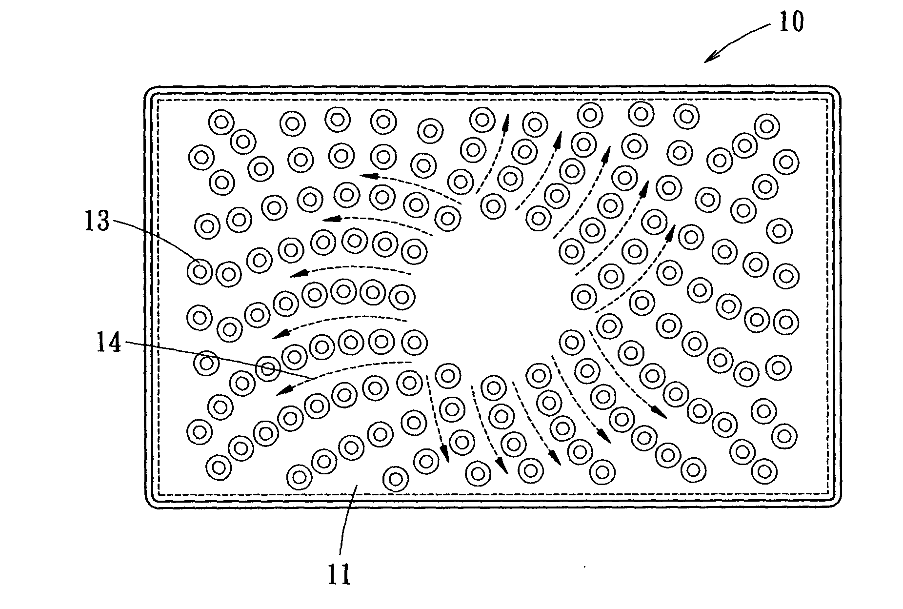
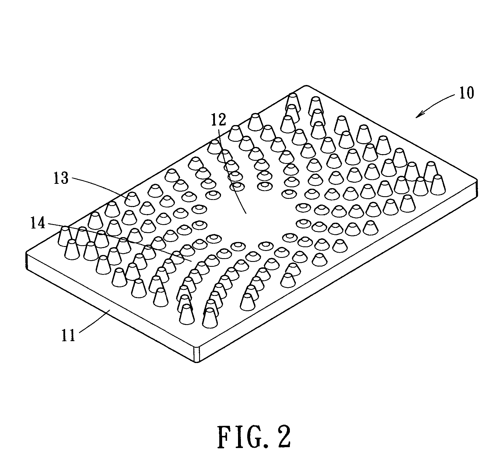
[0018] Referring to FIG. 2, a perspective view of a top lid is illustrated. As shown, the top lid 10 is in a cuboid shape and includes a top panel 11 circumscribed by four side panels. The top lid 10 is made material with good thermal conductivity. The side panels around the top panel 11 may further include a plurality of fitting plates (not shown). The top panel 11 includes a circular flat region 12 at a center thereof and a plurality of independent heat dissipating fins 13 spirally arranged around the circular flat region 12. The heat dissipating fins 13 are preferably forged into conical shapes with large bottom surfaces and small top surfaces or tips. The heights of the heat dissipating fins 13 increase gradually from the central circular flat region 12 to a periphery of the top panel 11. A spiral channel 14 is thus formed allowing air to circulate through. The spiral channel 14 is particularly advantageous for guiding the spiral air flow generated by a cooling fan.

[0019]FIGS. ...


PUM


Abstract

An improved structure of a planar heat pipe, having a top lid and a bottom lid. The bottom lid can be engaged with the top lid. A wick structure and a working fluid are installed in the heat pipe. The top lid has a top panel, which has a central flat area and a plurality of independent heat dissipating fins spirally arranged around the flat area. Each of the heat dissipating fins has a cone shape, and the height of the heat dissipating fins gradually increases from the center to the periphery of the top lid. A spiral heat circulating path is thus formed on the top lid. Thereby, when the cooling fan generates cooling air flow downwardly, an air impingement is formed upon the flat region of the top lid. The heat accumulated in the central flat region is then dissipated by the heat dissipating fins with an enhanced efficiency.

Description

BACKGROUND OF THE INVENTION [0001] The present invention relates generally to an improved structure of a planar heat pipe and, more particularly, to a planar heat pipe used in a computer central processing unit or other electronic heat generating device. The planar heat pipe has high thermal conductivity to dissipate effectively dissipate heat generated by the computer central processing unit or the electronic heat generating device, such that the heat generating device can operate under a uniform temperature. [0002] The development of the computer information technology greatly advances of the designs in the computer related field. For the conventional computer, the operation speed is relatively slow, and the cooling device with a fin-type heat sink and a cooling fan is sufficient. Recently, the clock pulse of the central processing unit has exceeded 1 GHz or even 3 GHz. As the heat generated by the central processing unit is proportional to the clock pulse. The conventional coolin...

Claims


Application Information

Patent Timeline
Patent Type & Authority Applications(United States)
IPC IPC(8): H01L23/427H01L23/467
CPCH01L23/427H01L23/467H01L2924/0002H01L2924/00F28D15/0233F28D15/046F28F3/044F28F2215/04
Inventor WANG, CHIN WENWANG, PEI CHOAWANG, CHING CHUNG
Owner PYROSWIFT HOLDING CO LIMITED
Why Eureka
Try Eureka