<<< 'High debris content strainer' >>>

Inactive Publication Date: 2005-03-03
LAING DAVID A
View PDF50 Cites 12 Cited by
  • Summary
  • Abstract
  • Description
  • Claims
  • Application Information

AI Technical Summary

Benefits of technology

[0010] A strainer for filtering a contaminated fluid flow having a high debris content. The strainer comprises: a cylindrical porous member disposed in the contaminated fluid flow and has a first outer surface upstream of the flow and a second inner surface downstream of the flow, wherein the high debris content lodges against the first outer surface and wherein the cylindrical porous member defines an inner region; a plurality of debris removal

Problems solved by technology

However, these filter cartridges require frequent replacement which, in turn, requires the fuel flow to be interrupted during replacement.
Interruption of the fuel oil flow will shut down the ship's main engines, thereby rendering the ship incapable of maneuvering.
This can be catastrophic where the ship is in tight quarters, e.g., during docking

Method used


Image

  • &lt;&lt;&lt; 'High debris content strainer' &gt;&gt;&gt;
  • &lt;&lt;&lt; 'High debris content strainer' &gt;&gt;&gt;
  • &lt;&lt;&lt; 'High debris content strainer' &gt;&gt;&gt;

Examples


Embodiment Construction

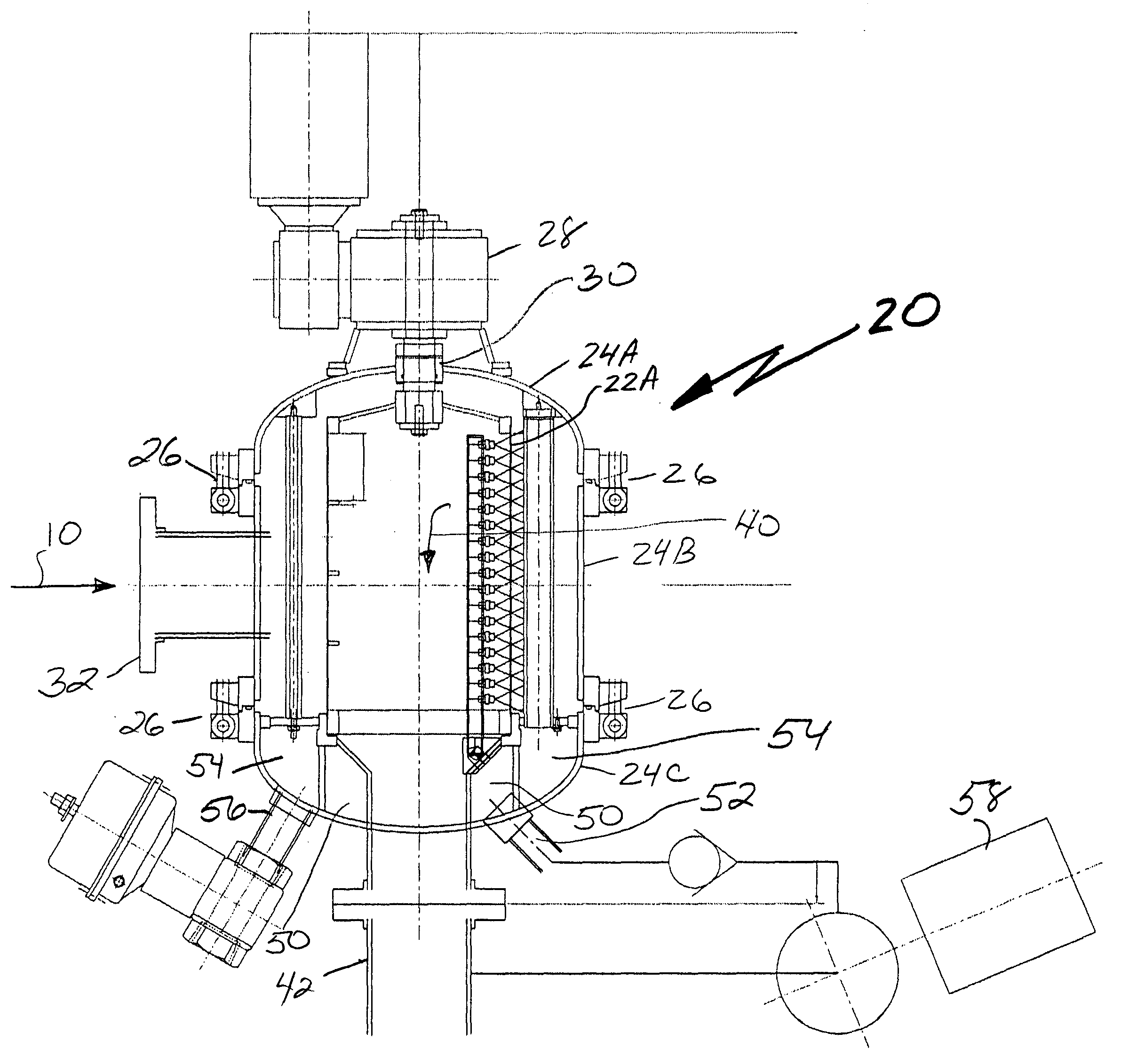
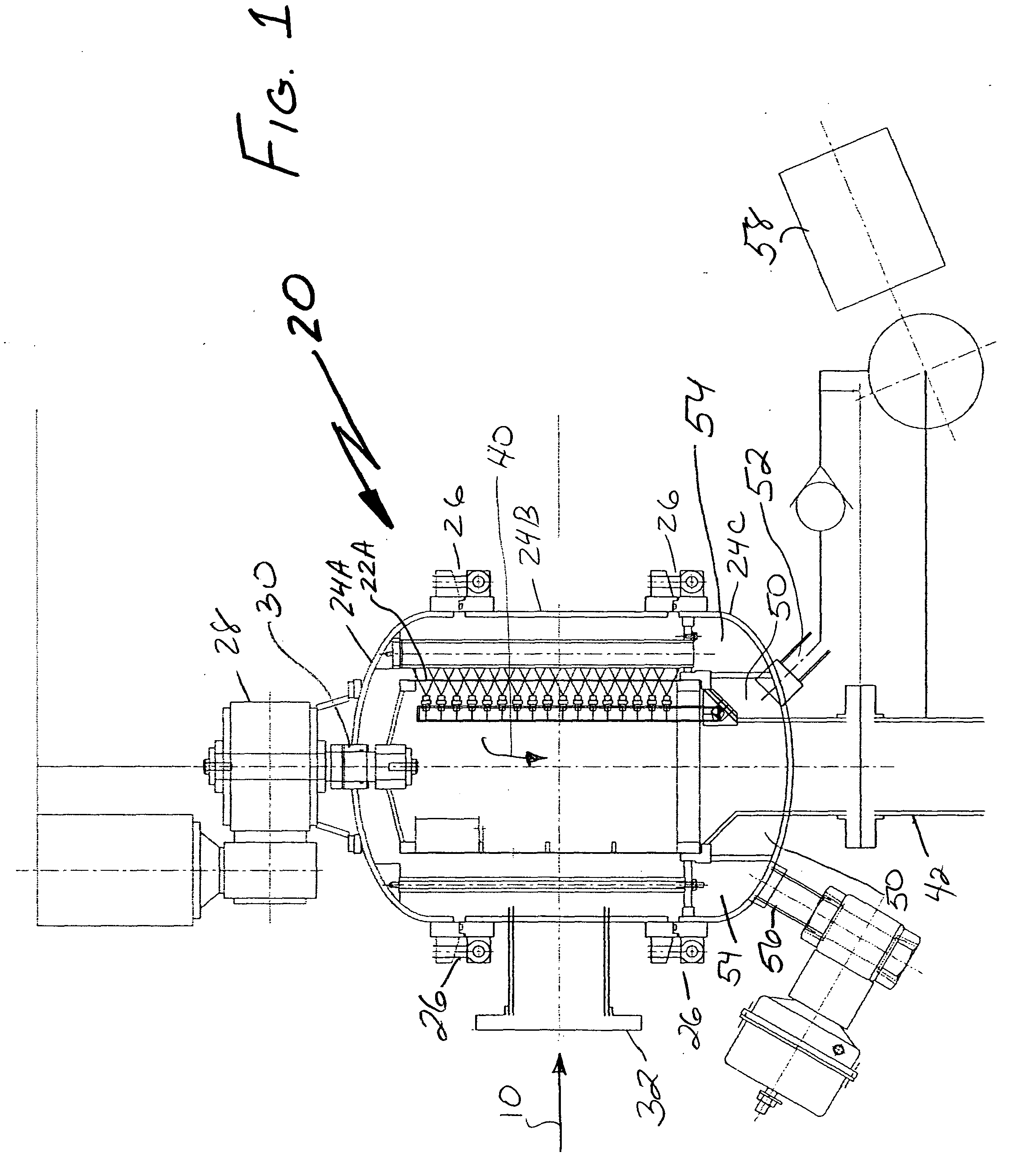
[0015] The present invention 20 is a high debris content strainer which is designed to handle a fluid flow, (e.g., water) with a higher amount of solid material than is normal for a strainer.

[0016] The strainer 20 achieves this by comprising more screen area than is typical for the fluid flow rate and by including four debris removal assemblies (e.g., discharge tube and brush / scraper, and even a backwash spray) around the screen. In particular, the present invention 20 comprises a cylindrically-shaped strainer screen 22 (e.g., a {fraction (1 / 32)} inch screen) that is rotatably-mounted inside a strainer housing which comprises an upper shell 24A, a central shell 24B and a lower shell 24C that are releasably-coupled to each other using speed clamp devices 26. A motor 28 (e.g., 1 HP motor) and spindle 30 effect the rotation of the strainer screen 22; a controller, not shown, controls the operation of the motor 28.

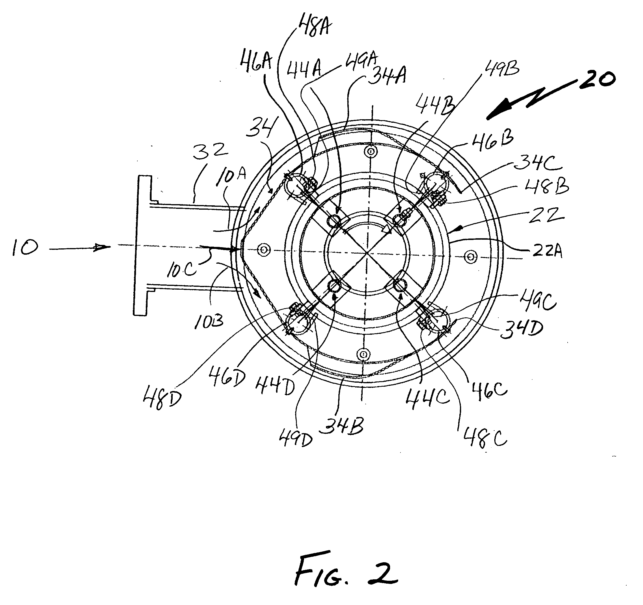
[0017] The contaminated fluid flow 10 enters the strainer 20 via an inp...


PUM

PropertyMeasurementUnit
Angleaaaaaaaaaa
Lengthaaaaaaaaaa
Flow rateaaaaaaaaaa

Abstract

A high debris content strainer that utilizes a cylindrically-shaped screen having four removal assemblies positioned evenly around the screen periphery. Each removal assembly includes a backwash spray bar on the downstream side of the screen and a scraper/brush and discharge tube on the upstream side of the screen where the debris lodges during filtering. The screen is rotatably-mounted inside a strainer housing. A shroud surrounds ¾ of the screen periphery and includes an opening directly adjacent an input fluid flow line, as well as scoops on opposing sides of the shroud. The shroud evenly distributes the contaminated fluid flow around the screen. When cleaning the screen is desired, the screen is rotated while the backwash spray bars are activated and, in combination with the scraper/brushes, the debris is dislodged from the upstream surface of the screen and directed into the discharge tubes which divert the contaminants to a discharge pipe.

Description

BACKGROUND OF THE INVENTION [0001] 1. Field of Invention [0002] This invention relates generally to filter devices and, more particularly, to filters for fluid flows having high debris content. [0003] 2. Description of Related Art [0004] It is well-known that the mechanical cleaning of a filter surface can be accomplished by having a brush or scraper drag along the filter surface where deposits have accumulated. [0005] In certain configurations, the brush or scraper is mounted at one end between two walls but with a significant portion of the brush or scraper projecting beyond the walls. Such configurations are shown in U.S. Pat. No. 148,557 (Gillespie et al.); U.S. Pat. No. 556,725 (Farwell); U.S. Pat. No. 740,574 (Kohlmeyer) and U.S. Pat. No. 793,720 (Godbe). In conventional filter systems, the particulate contaminants are driven off the filter surface and are deposited in a hopper or tank along with the fluid being filtered, thus discarding large amounts of the fluid being filter...

Claims


Application Information

Patent Timeline
IPC IPC(8): B01D29/11
CPCB01D29/114B01D29/682B01D29/70B01D29/902B01D29/94
Inventor LAING, DAVID A.
Owner LAING DAVID A
Why Eureka
Try Eureka