

Liquid-crystal composition
- Summary
- Abstract
- Description
- Claims
- Application Information
AI Technical Summary
Benefits of technology
Problems solved by technology
Method used
Image

Examples
synthesis example 1-1
1 Synthesis Example 1-1
Synthesis of Compound (S1-1-8)
[0350]
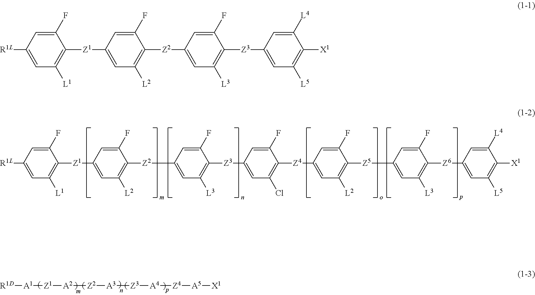
[0351]Based on the above Scheme 10, a synthesis scheme of compound (S1-1-8) being a compound represented by formula (1-1) will be explained.
Synthesis of Compound (S1-1-2)
[0352]To a reaction vessel under a nitrogen atmosphere, 88.3 g of (S1-1-1), 7.54 g of a catalyst, and 900 mL of tetrahydrofuran (THF) were added, and a THF solution of 2 mol / L of butylmagnesium chloride was added dropwise thereto at room temperature, and the resultant mixture was refluxed for 4 hours. The resultant reaction mixture was cooled to room temperature, toluene was added thereto, and the resultant mixture was washed with 1 N-hydrochloric acid and water. After drying over magnesium sulfate, the solvent was distilled off under a reduced pressure. The resultant product was purified by means of silica gel column chromatography by using heptane as the eluent, and the resultant purified product was dried under a reduced pressure, and thus 75.7 g of (S1-1...
synthesis example 1-2
2 Synthesis Example 1-2
Synthesis of Compound (S1-2-1), Compound (S1-3-1) and Compound (S1-4-1)
[0366]
[0367]The unit of the phase transition point described above is ° C.
[0368]Compounds (S1-2-1), (S1-3-1) and (S1-4-1) were prepared using a suitable reagent with the method in Synthesis Example 1-1.
(1) Physical Properties of Compound (S1-2-1)
[0369]Mother liquid crystal A having a nematic phase was prepared by mixing four compounds described as the mother liquid-crystal A. The physical properties of mother liquid crystal A were as described below.
[0370]Maximum temperature (TNI)=71.7° C.; dielectric anisotropy (Δ∈)=11.0; refractive index anisotropy (Δn)=0.137.
[0371]Liquid-crystal composition C including 90% of mother liquid crystal A and 10% of (S1-2-1) obtained in Synthesis Example 2 was prepared. The values of the physical properties of liquid-crystal composition C obtained were determined, and extrapolated values of the physical properties of liquid-crystal compound (S1-2-1) were calcu...
synthesis example 1-5
3 Synthesis Example 1-5
Synthesis of Compound (S1-5-3)
[0380]
[0381]Based on the above Scheme 11, a synthesis scheme of compound (S1-5-3) being a compound represented by formula (1-1) will be explained.
(1) Synthesis of Compound (S1-5-3)
[0382]Compounds (S1-1-2) to (S1-5-1) were prepared in a manner similar to the technique for synthesizing compounds (S1-1-5) to (S1-1-6) in Synthesis Example 1-1. Specifically, (S1-1-2) was used in place of (S1-1-5). Compounds (S1-5-1) to (S1-5-3) were prepared in a manner similar to the technique for synthesizing compounds (S1-1-6) to (S1-1-8) in Synthesis Example 1-1. Specifically, (S1-5-1) was used in phase of (S1-1-6), and (S1-5-2) was used in place of (S1-1-7). The phase transition temperature of compound (S1-5-3) obtained was as described below.
[0383]Phase transition temperature (° C.): K 63.1 N 88.5 I.
(2) Physical Properties of Liquid-Crystal Compound (S1-5-3)
[0384]Liquid-crystal composition F including 85% of mother liquid crystal A and 15% of (S1...
PUM
 Abstract
Description
Claims
Application Information