Optical recording medium

Inactive Publication Date: 2009-01-22
RICOH KK
View PDF6 Cites 8 Cited by
  • Summary
  • Abstract
  • Description
  • Claims
  • Application Information

AI Technical Summary

Benefits of technology

[0022]It is still further preferred that, in the optical recording medium mentioned above, the recording layer of each of the multiple information layers except for the information layer located at the furthermost back from the side of laser beam irradiation includes at least one element which improves the light absorption index k for a light having a wavelength of 405 nm to from 0.3 to 0.9.
[0023]It is still further preferred that, in the optical re

Problems solved by technology

However, when such a translucent layer is excessively thin (or not provided), the reflectivity decreases, resulting in difficulty in recording and playing.
Thus, in a structure of dual layers, which is desired to have a thin reflective layer as described above, such a recording layer has a drawback that formation of minute marks is difficult.
Thus, it is difficult to apply the structure of a phase change optical recording medium to a WORM optical recording medium.
However, the technology is related to a p

Method used


Image

  • Optical recording medium
  • Optical recording medium
  • Optical recording medium

Examples


example 1

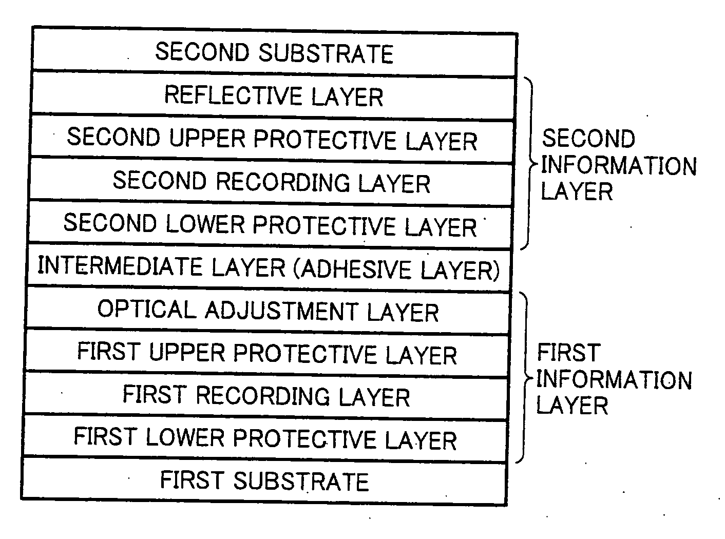
[0107]On a first substrate formed of a polycarbonate resin which has a diameter of 12 cm, a thickness of 0.59 mm, and a continuous wobbling groove for tracking guide having a track pitch of 0.4 μm with a depth of 30 nm on one side, a first lower protective layer of a mixture of ZnS and SiO2 with a molar ratio (%) of 80:20 having a thickness of 50 nm is formed by an RF magnetron sputtering method with a sputtering power of 4 kW in an Ar flowing rate of 15 sccm.

[0108]Next, with a sputtering power of 0.8 kW in an Ar flowing rate of 15 sccm, a first recording layer having a thickness of 7.5 nm is formed by an RF magnetron sputtering method using a Bi2O3 target.

[0109]Next, with a sputtering power of 4 kW in an Ar flowing rate of 15 scam, a first upper protective layer of a mixture of ZnS and SiO2 with a molar ratio (%) of 80:20 having a thickness of 20 nm is formed by an RF magnetron sputtering method.

[0110]Next, with a sputtering power of 2 kW in an Ar flowing rate of 15 sccm, an optica...

examples 8 to 14

[0121]The WORM optical recording media having two information layers of Examples 8 to 14 are manufactured in the same manner as in Examples 1 to 7 except that an Al2O3 layer having a layer thickness of 10 nm is formed between the first substrate and the first lower protective layer.

[0122]PRSNR is measured for the WORM optical recording media. The results are that PRSNR of Examples 8 to 14 increases by 4 to 6 in comparison with that of Examples 1 to 7.

example 15

[0123]On a first substrate formed of a polycarbonate resin which has a diameter of 12 cm, a thickness of 0.59 mm, and a continuous wobbling groove for tracking guide having a track pitch of 0.4 μm with a depth of 30 nm on one side, a first lower protective layer of a mixture of ZnS and SiO2 with a molar ratio (%) of 80:20 having a thickness of 50 nm is formed by an RF magnetron sputtering method with a sputtering power of 4 kW in an Ar flowing rate of 15 sccm.

[0124]Next, with a sputtering power of 0.8 kW in an Ar flowing rate of 15 sccm, a first recording layer having a thickness of 7.5 nm is formed by an RF magnetron sputtering method using a target having the composition ratio shown in Table 2. The results (absorption index k and refraction index n of each material for the recording layers measured by spectroscopic ellipsometer are shown in Table 2.

[0125]Next, with a sputtering power of 4 kW in an Ar flowing rate of 15 sccm, a first upper protective layer of a mixture of ZnS and S...


PUM


Abstract

An optical recording medium including a first substrate, multiple information layers in which each of the multiple information layers except for an information layer located at a furthermost back relative to the side of laser beam irradiation includes a recording layer, an upper protective layer and an optical adjustment layer having an absorption index k of from 0.05 to 0.20 to a light having a wavelength of 405 nm arranged in this order from the side of laser beam irradiation; and
    • intermediate layers provided between the multiple information layers.

Description

BACKGROUND OF THE INVENTION[0001]1. Field of the Invention[0002]The present invention relates to an optical recording medium, and more particularly to a write once read many (WORM) optical recording medium in which dense recording is possible in a blue laser beam wavelength area.[0003]2. Discussion of the Background[0004]Recently, a dual layer structure has been proposed to increase the data capacity of a write once read many (WORM) optical recording medium.[0005]In such a situation, there is proposed a technology with regard to a WORM optical recording medium for a blue laser beam, which is a recording layer (inorganic layer) formed of mainly a bismuth oxide is provided instead of an organic material thin layer functioning as a heat generation layer by light absorption function and a recording layer which uses changes of refraction (realpart of complex refraction index) ascribable to decomposition and alteration.[0006]With regard to a WORM optical recording medium having a dual lay...

Claims


Application Information

Patent Timeline
IPC IPC(8): G11B7/24G11B7/24038G11B7/243G11B7/258G11B7/259
CPCG11B7/0037G11B7/24G11B7/24038G11B7/252G11B7/259G11B2007/24328G11B2007/2431G11B2007/24312G11B2007/24314G11B2007/2432G11B2007/24308
Inventor FUJII, TOSHISHIGESEKIGUCHI, HIROYOSHISASA, NOBORUHAYASHI, YOSHITAKAFUJIWARA, MASAYUKISASAKI, TOSHIHIDE
Owner RICOH KK
Why Eureka
Try Eureka