
Vacuum regulating valve

a valve seat and vacuum technology, applied in the direction of valve details, valve arrangement, spindle sealing, etc., can solve the problem of limited movement of the piston away from the valve seat, and achieve the effect of accurate determination and regulation

Active Publication Date: 2005-03-03
SMC CORP
View PDF4 Cites 20 Cited by
  • Summary
  • Abstract
  • Description
  • Claims
  • Application Information

AI Technical Summary

Benefits of technology

[0013] The valve element can be separated from the valve seat and valve opening can be accurately determined and regulated by the valve opening regulating unit including the valve opening setting shaft for determining the working position of the piston and the driving mechanism capable of continuously moving the valve opening setting shaft in either of the opposite directions for a necessary displacement.

Problems solved by technology

The piston comes into contact with the valve opening setting shaft and the movement of the piston away from the valve seat is limited to stop the piston at a desired operating position.

Method used


Image

  • Vacuum regulating valve
  • Vacuum regulating valve
  • Vacuum regulating valve

Examples


Embodiment Construction

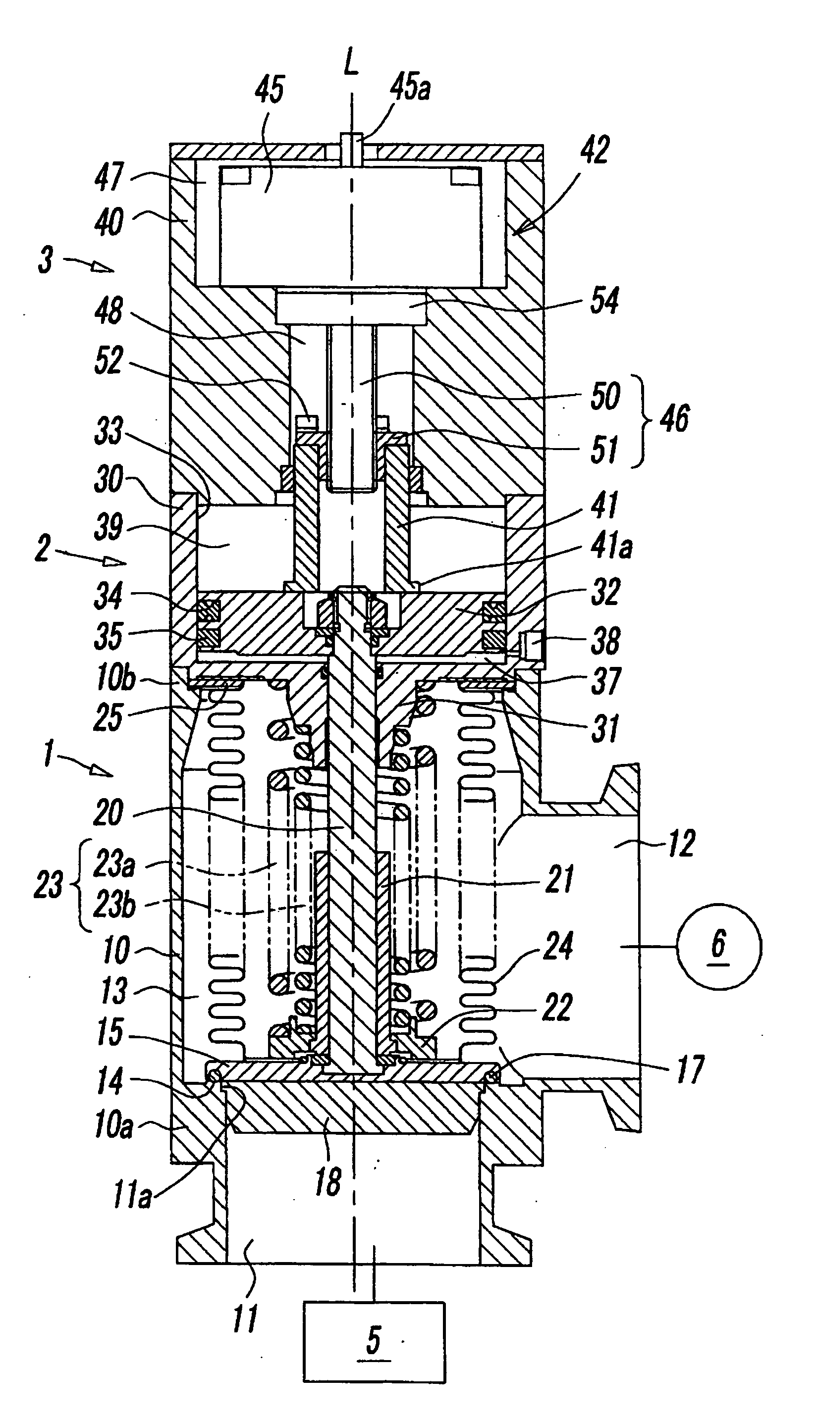
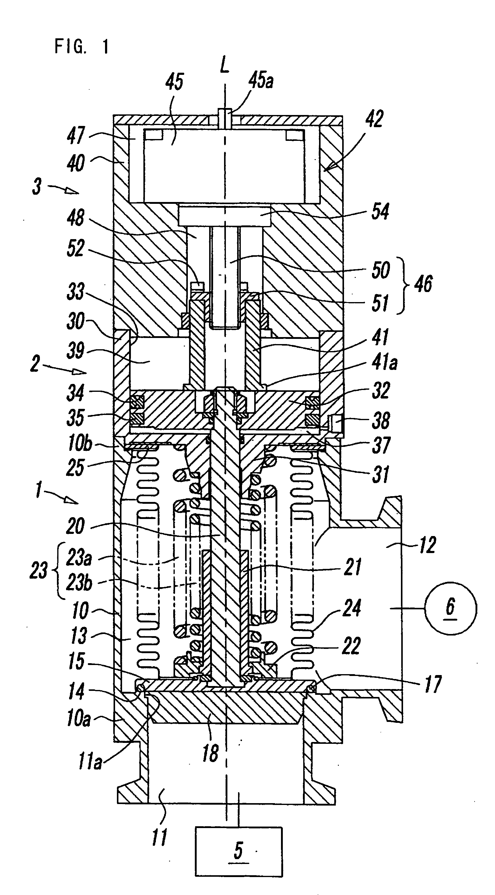
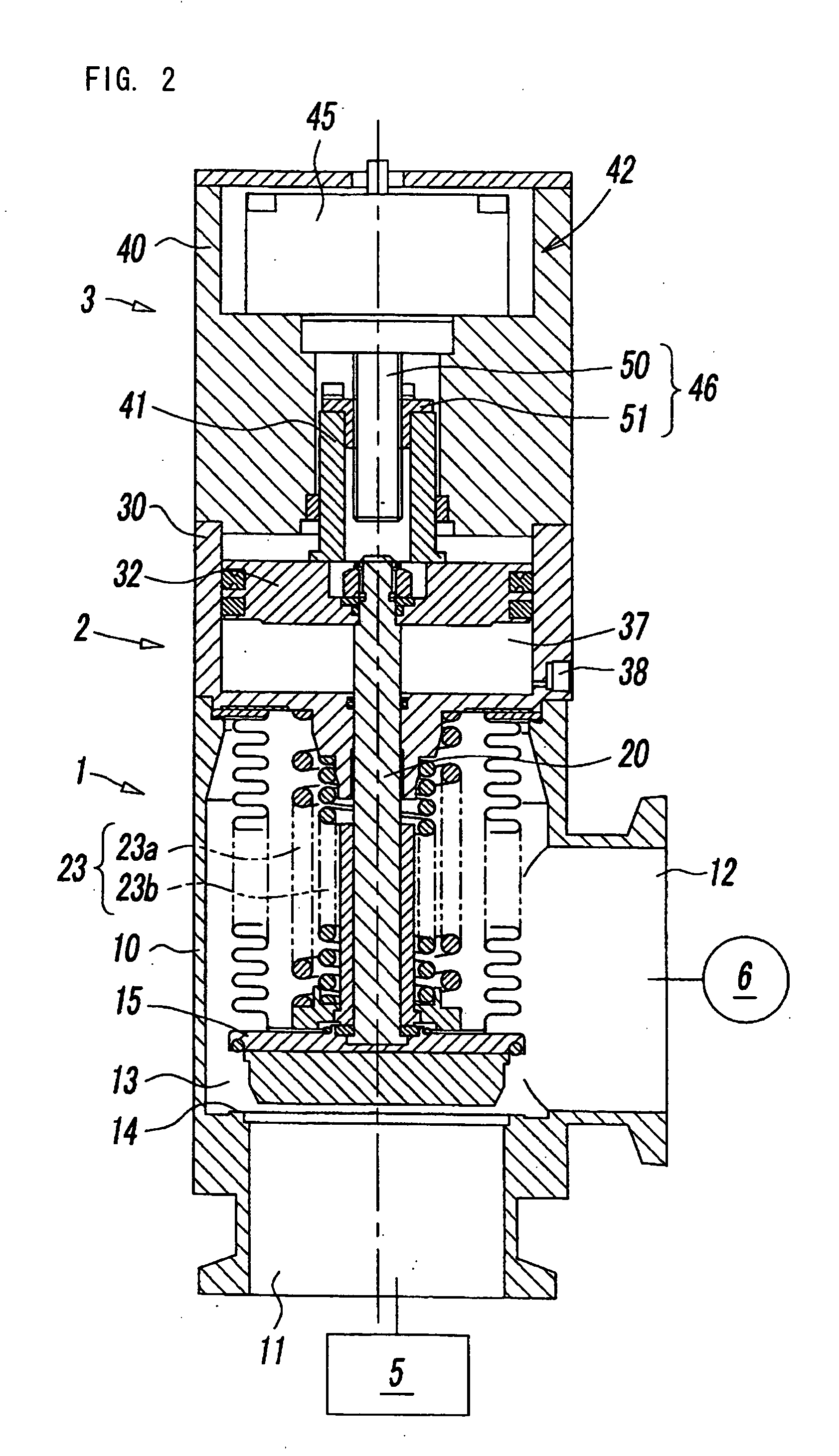
[0017] Referring to FIGS. 1 and 2, a vacuum regulating valve in a preferred embodiment according to the present invention consists of a valve unit 1 provided with a valve element 15 for opening and closing a passage 13, a cylinder actuator 2 for operating the valve element 15 to open and close the passage 13, and a valve opening regulating unit 3 for setting the valve element 15 at a desired valve position. The valve unit 1, the cylinder actuator 2 and the valve opening regulating unit 3 are arranged and joined in series along the axis L of the vacuum regulating valve.

[0018] The valve unit 1 has a hollow valve casing 10 of a shape substantially resembling a circular cylinder or a prism. The valve casing 10 is provided with a first main port 11 to be connected to a vacuum vessel 5, and a second main port 12 to be connected to a vacuum pump 6. The first main port 11 is formed in an end wall 10a of the valve casing 10 coaxially with the axis L. The second main port 12 is formed in a s...


PUM


Abstract

A vacuum regulating valve includes a valve casing provided with two main ports, a passage connecting the two main ports, a valve seat formed in the passage, a valve element capable of being seated on the valve seat, a valve stem extending from the valve element, and a piston attached to the free end of the valve stem. A valve opening setting unit includes a valve opening setting shaft having a free end held in contact with the back surface of the piston, and a driving mechanism capable of continuously axially moving the valve opening setting shaft to a desired position to set the piston at an operating position corresponding to a desired valve opening.

Description

BACKGROUND OF THE INVENTION [0001] 1. Field of the Invention [0002] The present invention relates to a vacuum regulating valve for regulating the pressure in an evacuated vacuum vessel for chemical reaction included in a physical or chemical machine or the like. [0003] 2. Description of the Related Art [0004] A chemical process, such as an etching process, is carried out in a vacuum vessel included in a semiconductor device fabricating system. The vacuum vessel is evacuated at a negative pressure by a vacuum pump. A pressure regulating valve is placed in an external line connecting the vacuum vessel to the vacuum pump. A pressure regulating valve disclosed in JP-A No. 8-178126 has two ports connected, respectively, to a vacuum vessel and a vacuum pump, internal passage connecting the two ports, a valve seat formed in the internal passage, a valve element to be seated on the valve seat to close the pressure regulating valve, and a piston for operating the valve element. The stroke of...

Claims


Application Information

Patent Timeline
IPC IPC(8): F16K31/04F16K37/00F16K41/10F16K31/122F16K51/02
CPCF16K31/047F16K51/02F16K41/10
Inventor KAJITANI, MASAO
Owner SMC CORP
Features
  • Generate Ideas
  • Intellectual Property
  • Life Sciences
  • Materials
  • Tech Scout
  • Unparalleled Data Quality
  • Higher Quality Content
  • 60% Fewer Hallucinations
Learn More