Tiltable-body apparatus, and method of fabricating the same

Inactive Publication Date: 2005-03-03
CANON KK
View PDF16 Cites 22 Cited by
  • Summary
  • Abstract
  • Description
  • Claims
  • Application Information

AI Technical Summary

Benefits of technology

[0020] It is an object of the present invention to provide a tiltable-body apparatus with good strength and performance including a tiltable body which can be reciprocally tilted about

Problems solved by technology

In a microstructure with such torsion bars, however, since the torsion bar is likely to bend in a direction perpendicular to its longitudinal axis, the microstructure can be easily affected by external vibrations and the longitudinal axis of the torsion bar can be easily shifted.
Accordingly, it is difficult to attain an accurate driving in such a microstructure.
Therefore, when the above optical scanner is used in an optical scanning

Method used


Image

  • Tiltable-body apparatus, and method of fabricating the same
  • Tiltable-body apparatus, and method of fabricating the same
  • Tiltable-body apparatus, and method of fabricating the same

Examples


first embodiment

[0105] A micro-optical scanner of a first embodiment according to the present invention will be described with reference to FIG. 10, FIG. 11A, FIG. 11B, FIG. 12 and FIG. 13.

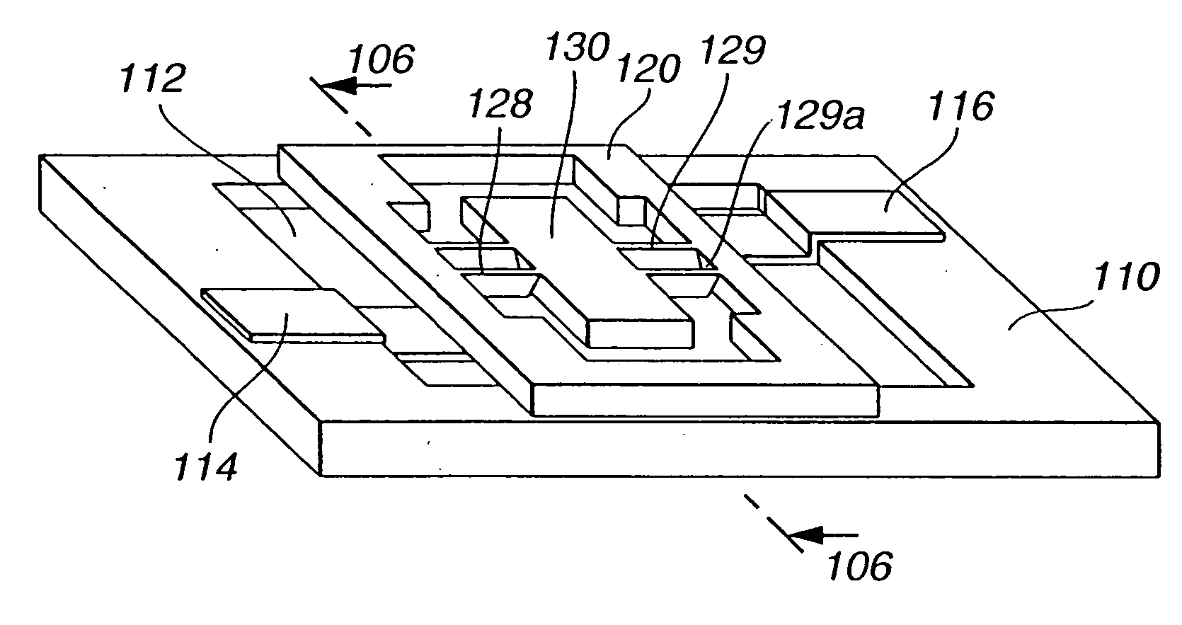
[0106] In the micro-optical scanner of the first embodiment, a recess 112 is formed on a glass substrate 110. A pair of driver electrodes 114 and 116 and a mirror support 132 of a triangular prism are arranged on the bottom of the recess 112. The mirror support 132 can be omitted. In a single crystal silicon thin plate 120, two sets of torsion springs 128 and 129 and a planar mirror 130 are integrally formed by bulk micromachining techniques. Each of the torsion springs 128 and 129 has a cross section of symmetrical V-shape, as illustrated in FIG. 13. This shape is a heptagonal shape with an internal angle of 289.4 degrees, and has two portions slant to a plane of the mirror 130.

[0107] The mirror 130 has a flat surface coated with a highly-reflective material, and is supported by the V-shaped torsion springs 128...

second embodiment

[0130] a micro-optical scanner according to the present invention will be described with reference to FIG. 18, FIG. 19A, FIG. 19B, and FIG. 20. The cross-sectional view of FIG. 19A taken along a line 309 is the same as FIG. 12.

[0131] Also in the second embodiment of the micro-optical scanner, a recess 312 is formed on a glass substrate 310. A pair of driver electrodes 314 and 316 and a mirror support 332 of a triangular prism are arranged on the bottom of the recess 312. In a silicon plate 320, torsion springs 322 and 324 and a mirror 330 are integrally formed by bulk micromachining techniques. Each of the torsion springs 322 and 324 has a cross section of X-shape, as illustrated in FIG. 20. This shape is a dodecagonal shape with four internal angles of more than 180 degrees, is 180-degree rotationally symmetric, and has portions slant to the plane of the mirror 330.

[0132] The mirror 330 has a flat surface coated with a highly-reflective material, and is supported by the X-shaped t...

third embodiment

[0157]FIG. 26 is a perspective view illustrating a micro-optical scanner according to the present invention. FIG. 27A is a view illustrating a disassembled structure of the micro-optical scanner to show its internal structure. FIG. 28 is a cross-sectional view of FIG. 26 taken along a line 606, illustrating cross sections of a single crystal thin plate 620 and torsion springs 628 and 629. The cross-sectional view of FIG. 27A taken along a line 609 is the same as FIG. 12.

[0158] Also in the third embodiment of the micro-optical scanner, a recess 612 is formed on a glass substrate 610. A pair of driver electrodes 614 and 616 and a mirror support 632 of a triangular prism are arranged on the bottom of the recess 612. In the silicon plate 620, torsion springs 628 and 629 and a mirror 630 are integrally formed by bulk micromachining techniques. Each of two sets of the torsion springs 628 and 629 consists of a pair of leaf-shaped torsion bars 622 and 623; 624 and 625, and its cross section...


PUM


Abstract

The tiltable-body apparatus including a frame member, a tiltable body, and a pair of torsion springs having a twisting longitudinal axis. The torsion springs are disposed along the twisting longitudinal-axis opposingly with the tiltable body being interposed, support the tiltable body flexibly and rotatably about the twisting longitudinal axis relative to the frame member, and include a plurality of planar portions, compliant directions of which intersect each other when viewed along a direction of the twisting longitudinal axis. A center of gravity of the tiltable body is positioned on the twisting longitudinal axis of the torsion springs.

Description

BACKGROUND OF THE INVENTION [0001] 1. Field of the Invention [0002] The present invention relates to a tiltable-body apparatus with a tiltable body which can be reciprocally tilted about a twisting longitudinal axis, such as micro-sensors for sensing mechanical amounts, micro-actuators, and optical micro-scanners, and a method of fabricating the tiltable-body apparatus. [0003] 2. Description of the Related Background Art [0004] It is well known that surface forces become more dominant than volume forces as the size of mechanical elements decreases and the influence of friction thus increases in such machines more than in normally-sized machines. Accordingly, in designing micro-machines, it is generally necessary to consider the reduction of the number of sliding portions and rotating portions as much as possible. [0005] A conventional optical scanner with a tiltable body oscillating about a twisting longitudinal axis will be described. FIG. 1 illustrates the optical scanner disclose...

Claims


Application Information

Patent Timeline
IPC IPC(8): B81B3/00G02B26/08G02B26/10
CPCB81B3/0051B81B3/0067B81B2201/038B81B2201/042B81B2203/0181Y10S359/904B81C2201/0133G02B26/0841G02B26/105Y10S359/90B81B2203/058G02B26/08
Inventor YASUDA, SUSUMUMIZUTANI, HIDEMASAYAGI, TAKAYUKISHIMADA, YASUHIROHIROSE, FUTOSHIKATO, TAKAHISA
Owner CANON KK
Why Eureka
Try Eureka