Method and apparatus for X-ray image correction

Active Publication Date: 2005-03-03
NIHON UNIVERSITY
View PDF2 Cites 20 Cited by
  • Summary
  • Abstract
  • Description
  • Claims
  • Application Information

AI Technical Summary

Benefits of technology

An advantage of the invention is that an X-ray image can be acquired correctly in an X-ray CT scanner having a rotary arm

Problems solved by technology

However, there are many problems to be solved in order to use a portable CT scanner actually.
One of the pro

Method used


Image

  • Method and apparatus for X-ray image correction
  • Method and apparatus for X-ray image correction
  • Method and apparatus for X-ray image correction

Examples


Embodiment Construction

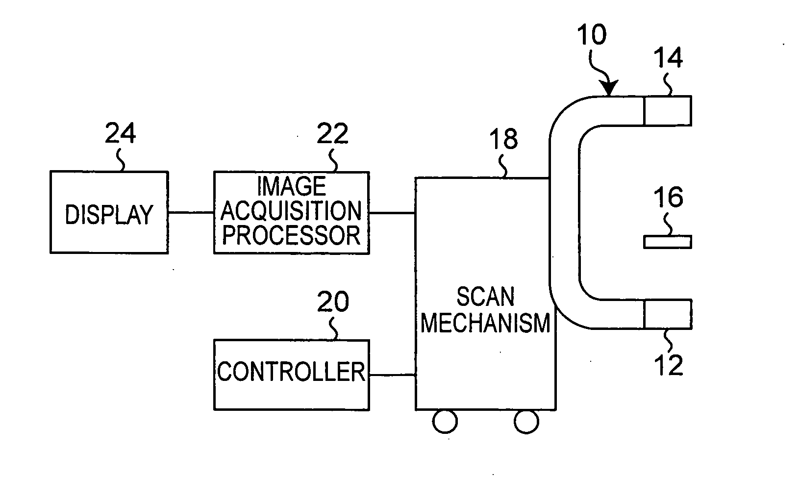
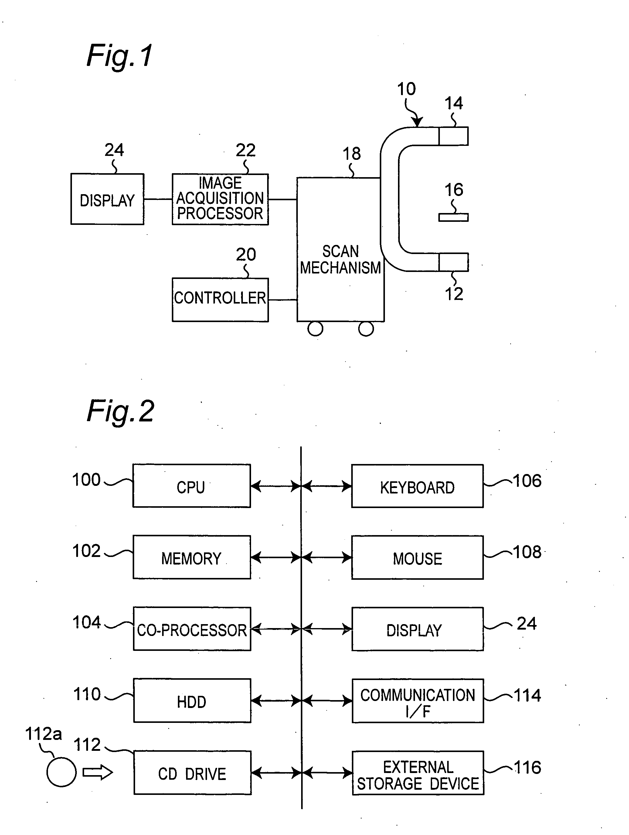
Referring now to the drawings, wherein like reference characters designate like or corresponding parts throughout the several views, FIG. 1 shows a portable X-ray CT scanner using a rotary arm 10 having a horizontal rotary axis. The rotary arm 10 has a shape similar to transversely tilted character U including two right-angle portions. In such a scanner, an X-ray source 12 is mounted at an end of the rotary arm 10, and a two-dimensional X-ray detector 14 is mounted at the other end of the rotary arm 10. The X-ray source 12 generates a corn beam of X-rays. The two-dimensional X-ray detector 14 is for example an X-ray photomultiplier. It receives incident X-rays to generate visible light, which is imaged with a charge-coupled device (CCD) camera and outputs electric signals. A head rest 16 to support a person's head to be examined is positioned around a rotation center between the X-ray source 12 and the X-ray detector 14. This CT scanner is used for dentistry, and the person's head ...


PUM


Abstract

In an X-ray computerized tomography scanner, a correction phantom embedding an X-ray absorbing object is put on or around a non-vertical rotary axis between an X-ray source and a two-dimensional X-ray detector, and two dimensional imaging data of the phantom is acquired. Then a locus of the X-ray absorbing material is determined in the two-dimensional imaging data, and based on the locus an ideal locus is obtained in the direction of the rotary axis. Next, a difference between the calculated position of the ideal locus and a measured position is determined in the direction of the rotary axis. The difference is used to correct deviation in the direction of the rotary axis.

Description

FIELD OF THE INVENTION The invention relates to X-ray computerized tomography scanner and in particular to correction of an X-ray CT image. RELATED ART A typical X-ray computerized tomography (CT) scanner has a gantry having an X-ray source and an X-ray detector both mounted to a rotary component thereof so as to oppose each other. A person to be examined lying on a bed movable vertically and horizontally is positioned between the X-ray source and the X-ray detector. While the gantry is rotated around the person on the bed, a corn beam of X-rays is generated by the X-ray source moving along a circular orbit to irradiate the person, and X-rays transmitting the person are received by the X-ray detector. In the case of a helical CT scanner, X-ray imaging is continued while the person on the bed is kept moving. The detection data are calculated to reconstruct an X-ray tomography image of the person, and the reconstructed image is displayed on a display device. A gantry of an X-ray CT...

Claims


Application Information

Patent Timeline
IPC IPC(8): A61B6/00A61B6/03
CPCA61B6/032A61B6/4085A61B6/027A61B6/463A61B6/583A61B6/4441
Inventor ARAI, YOSHINORISUZUKI, MASAKAZU
Owner NIHON UNIVERSITY
Why Eureka
Try Eureka