Sliding bearing

Active Publication Date: 2005-03-03
TAIHO INDUSTRIES CO LTD +1
View PDF6 Cites 21 Cited by
  • Summary
  • Abstract
  • Description
  • Claims
  • Application Information

AI Technical Summary

Benefits of technology

[0008] In view of the foregoing, the present invention is intended to provide a sliding bearing which is capable of suppressing the ingress of a foreign particle in large quantities onto the sliding surface

Problems solved by technology

However, this also causes a reduction in the oil pressure within a main hole, presenting a problem that an oil pressure required by the engine cannot be secured.
In the sliding bearing disclosed in the patent literature 2, the termination of the oil groove in the region of the crush reliefs allows the oil pressure in the

Method used


Image

  • Sliding bearing
  • Sliding bearing
  • Sliding bearing

Examples


Embodiment Construction

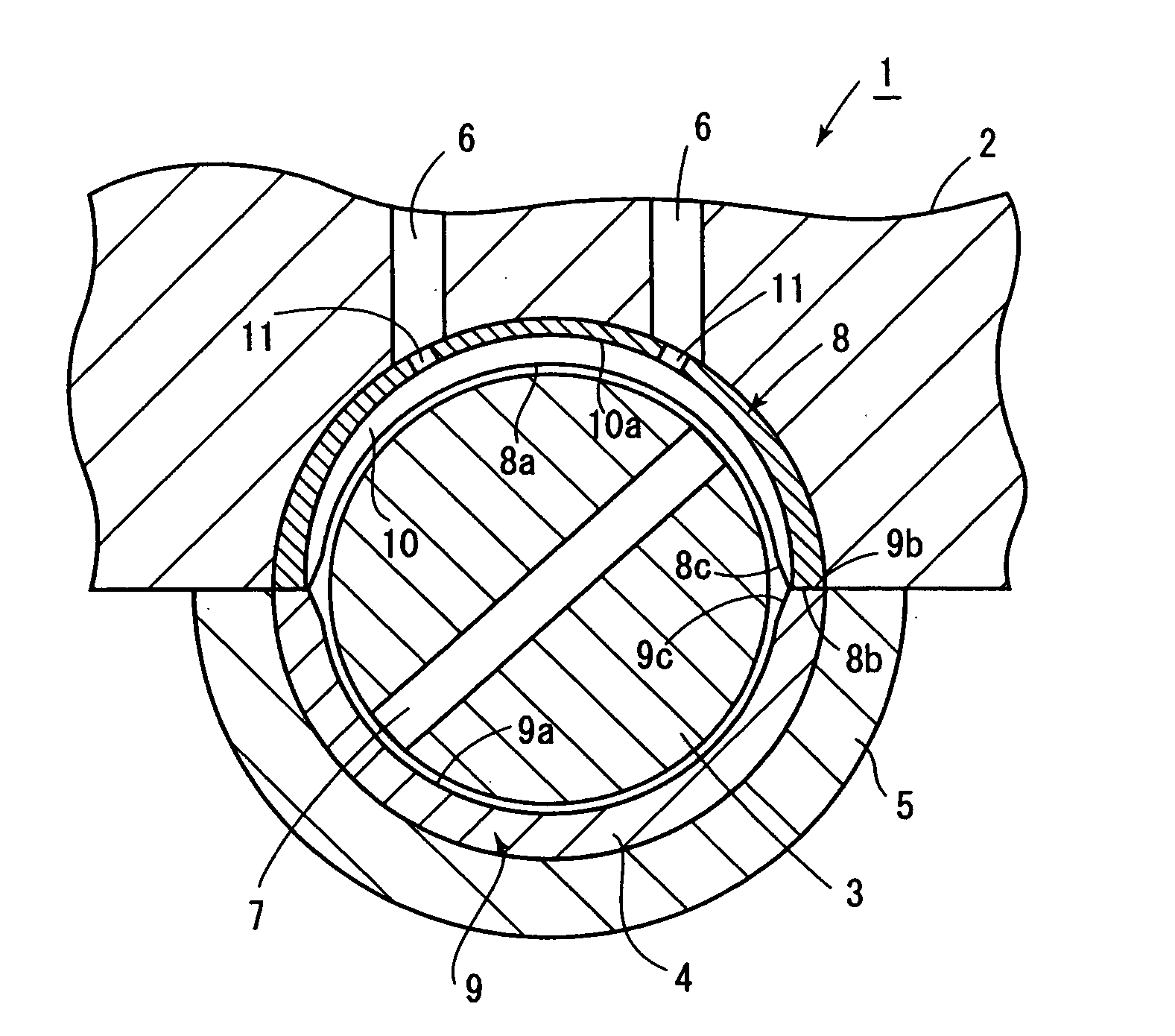
[0023] Initially referring to FIG. 1 to describe a first embodiment of the present invention, there is shown a cross section of an engine 1. The engine 1 comprises a cylinder block 2, a crankshaft 3 and a sliding bearing 4. The crankshaft 3 is slidably journaled by the sliding bearing 4, which is secured to the cylinder block 2 by a cap 5.

[0024] The cylinder block 2 is formed with a pair of lubricating oil passages 6 which feed a lubricating oil from an oil pump to a space between the crankshaft 3 and a sliding bearing 4, and the crankshaft 3 is formed with a diametrically extending lubricating oil feed passage 7.

[0025] As the crankshaft 3 rotates, the lubricating oil disposed between the crankshaft 3 and the bearing 4 passes through the lubricating oil feed passage 7 and thence passes through the crankshaft 3 to be fed to a space, not shown, between the crankshaft and the connecting rod bearing.

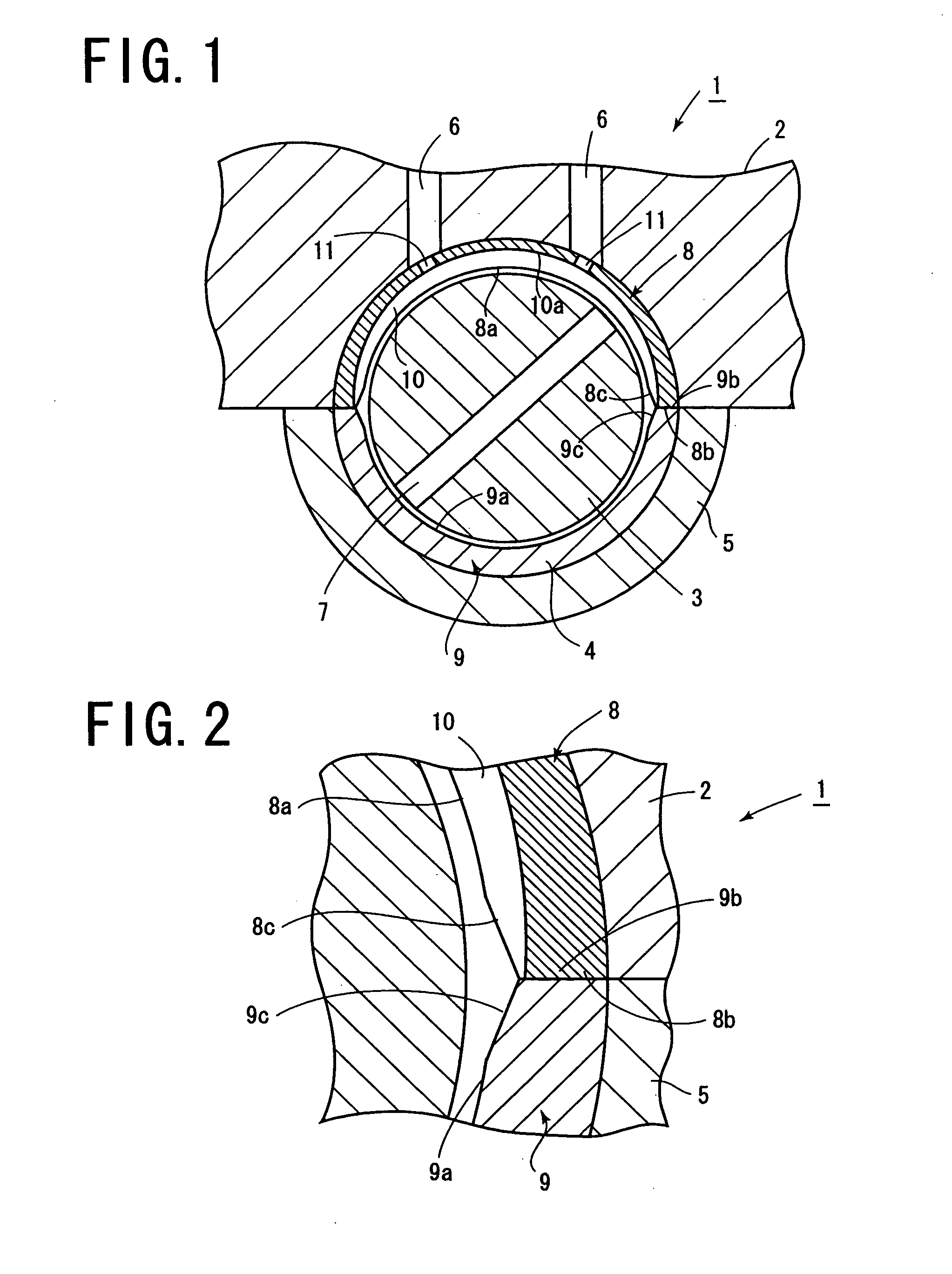
[0026] The sliding bearing 4 is constructed by an upper split bearing half 8 and a lo...


PUM


Abstract

A sliding bearing 4 is constructed by an upper split bearing half 8 and a lower split bearing half 9. The upper split bearing half 8 has a sliding surface 8a, in which an oil groove 10 which allows an lubricating oil to flow therein is formed over the entire circumferential extent of the sliding surface 8a. The oil groove extends through a crush relief 8c to be open to a junction area 8b, and the oil groove has a bottom 10a which is formed so that a portion disposed toward the junction area as considered in the circumferential direction of the crush relief is located closer to the center of the upper split bearing half in comparison to a central portion. An ingress in large quantities of foreign particles within the oil groove onto the sliding surface of the sliding bearing and into a connecting rod bearing after passing through a lubricating oil feed passage is suppressed, and an oil leakage through the crush relief is reduced, allowing a lubricating oil pressure to be secured and augmented.

Description

FIELD OF THE INVENTION [0001] The present invention relates to a sliding bearing, and more particularly, to a sliding bearing in which one of split bearing halves is formed in its sliding surface with an oil groove which allows a lubricating oil to flow therethrough. DESCRIPTION OF THE PRIOR ART [0002] A sliding bearing is known in the art comprising a pair of split bearing halves and in which one of split bearing halves is formed in its sliding surface with an oil groove which allows a lubricating oil to flow therearound in the circumferential direction and in which crush reliefs are formed at the junction area between the both split bearing halves toward the sliding surface. [0003] A sliding bearing of the kind described is known in which the oil groove is formed over the entire circumferential extend of the split bearing half and is open to the junction between the split bearing halves through crush reliefs (patent literature 1: Japanese Laid-Open Patent Application No. 109,215 / 1...

Claims


Application Information

Patent Timeline
IPC IPC(8): F16C33/06F16C9/04F16C33/10
CPCF16C9/02F16C33/1065F16C17/022F16C41/008F16C33/105F16C2360/22F16C33/046F16C33/10
Inventor YAMAZAKI, MASAOTAKAHASHI, MASAOHIKITA, YASUHIRONATSUME, JUNICHISHIBA, TOSHIMITSUKIKUCHI, TAKASHITERADA, TATSUHIROSHIMURA, TAKASHI
Owner TAIHO INDUSTRIES CO LTD
Why Eureka
Try Eureka