Electrolysis apparatus and water treatment method

a technology of electrolysis apparatus and water treatment method, which is applied in water/sewage treatment, water/sludge/sewage treatment, chemistry apparatus and processes, etc. it can solve the problems of increasing the size and weight of the apparatus, increasing the energy required for heating, and difficult to treat a large amount of liquid waste by batch treatment or quasi-continuous treatment, etc., to achieve the effect of reducing the cross-sectional area of channels, increasing the velocity of liquid flowing along the surface of electrodes, and increasing the efficiency of decomposition reaction

Active Publication Date: 2018-06-14
KURITA WATER INDUSTRIES LTD
View PDF4 Cites 2 Cited by
  • Summary
  • Abstract
  • Description
  • Claims
  • Application Information

AI Technical Summary

Benefits of technology

[0027]According to the present invention, the following advantageous effects may be achieved.
[0028]1) Since the container main body is sealed with the end members screwed in the container main body instead of a flanged lid, a once-through channel for the liquid to be treated is formed. This enables the cross-sectional area of channels to be reduced. Accordingly, the velocity at which the liquid flows along the surfaces of the electrodes can be increased, and bubbles can be removed from the surfaces of the electrodes. This increases the efficiency of the decomposition reaction on the surface of the electrodes.
[0029]2) The electrolysis apparatus does not include a large-thickness, large-size reactor or a member such as a flanged lid. This reduces the amount of energy lost during heating and the amount of energy lost due to heat dissipation.
[0030]3) The electrolysis apparatus includes an insulator that insulates the internal electrodes from the container main body. This enables control of the flow of current and reduces the risk of a current being diverted from the electrodes and directly passed into the container main body, which is referred to as “short path”. As a result, the electrolysis efficiency can be increased. Furthermore, the insulator supports the electrode plates and enables the electrode plates to be consistently arranged at predetermined intervals.
[0031]4) The bipolar electrode plates are disposed in the container main body so as to be parallel to the anode plate. This increases the area of the electrodes per volume and, consequently, the electrolysis efficiency.
[0032]5) The anode plate is made of a metal and integrated with the power supply rod into one component. This reduces the contact resistance of a power supply unit. In this case, also, the insulator disposed in the periphery of the electrodes enables control of the flow of current, reduces the risk of a current being diverted from the electrodes, and increases the electrolysis efficiency.

Problems solved by technology

However, it is difficult to treat a large amount of liquid waste by a batch treatment or a quasi-continuous treatment, because the amount of liquid waste that can be treated by one batch treatment or one quasi-continuous treatment is small.
This increases the size and weight of the apparatus.
Therefore, a large amount of energy is required for performing heating in the initial stage.
This also increases the amount of heat lost by heat dissipation.
Although the formation of bubbles is suppressed when electrolysis is performed under high-temperature, high-pressure conditions, it is not possible to prevent the formation of bubbles.
If bubbles are adhered to the surfaces of the electrodes, the contact efficiency between the liquid that is to be treated and the electrodes may be reduced, which results in, for example, a reduction in the reaction efficiency or an increase in the electrolysis voltage.
Although the bubbles can be washed away and removed by increasing the flow rate of the liquid that is to be treated, it is difficult to remove bubbles adhered on the surfaces of the electrodes because, in the structure employed in PTL 3, channels have a large cross-sectional area and the velocity (linear velocity) at which the liquid flows along the surfaces of the electrodes is low even when the flow rate of the liquid is high.
vi) Since the electrolysis apparatus includes metal electrodes, the efficiency with which organic substances are electrolyzed is low.
vii) When metal electrodes are used, it is not possible to employ a bipolar structure under high-temperature, high-pressure conditions, and increasing the area of internal electrodes included in one cylindrical tube requires installing cathodes and anodes separately.
This increases the complexity of the structure.

Method used


Image

  • Electrolysis apparatus and water treatment method
  • Electrolysis apparatus and water treatment method
  • Electrolysis apparatus and water treatment method

Examples


example 1

[0105]The raw water sample was electrolyzed with an electrolysis apparatus having the same structure as that illustrated in FIG. 6 except that the insulators were omitted, which included the anode plate 6 and did not include the bipolar electrode plates. The specifications of the electrolysis apparatus and the electrolysis conditions were set as follows.

[0106]

[0107]Container main body: Titanium container having an inside diameter of 8 mm, a length of 140 mm, and a side-wall thickness of 1 mm

[0108]Anode plate: Tabular conductive diamond electrode having a width of 6 mm, a length of 120 mm, and a thickness of 0.8 mm

[0109]

[0110]Temperature: 250° C.

[0111]Pressure: 7 MPa

[0112]Current density: 10 A / dm2

[0113]Flow rate: 3 mL / min

[0114]FIG. 19 illustrates the relationship between the amount of current input per liter of the raw water sample in the electrolysis treatment performed under the above conditions and the TOC concentration in the electrolyzed water.

example 2

[0115]An electrolysis treatment was performed as in Example 1, except that an iridium oxide electrode having the same dimensions as in Example 1 was used as an anode plate. FIG. 19 illustrates the results.

[0116]As is clear from the results shown in FIG. 19, the amount of current required for reducing the TOC concentration to 10 mg / L or less was 75 Ah / L in the case where the diamond electrode was used and 108 Ah / L in the case where the iridium oxide electrode was used. That is, it was possible to decompose the organic substances using the diamond electrode with a current efficiency that is about 1.5 times the current efficiency with which the organic substances were decomposed using the iridium oxide electrode. This confirms that using a diamond electrode enables efficient treatment of wastewater containing organic substances.

example 3

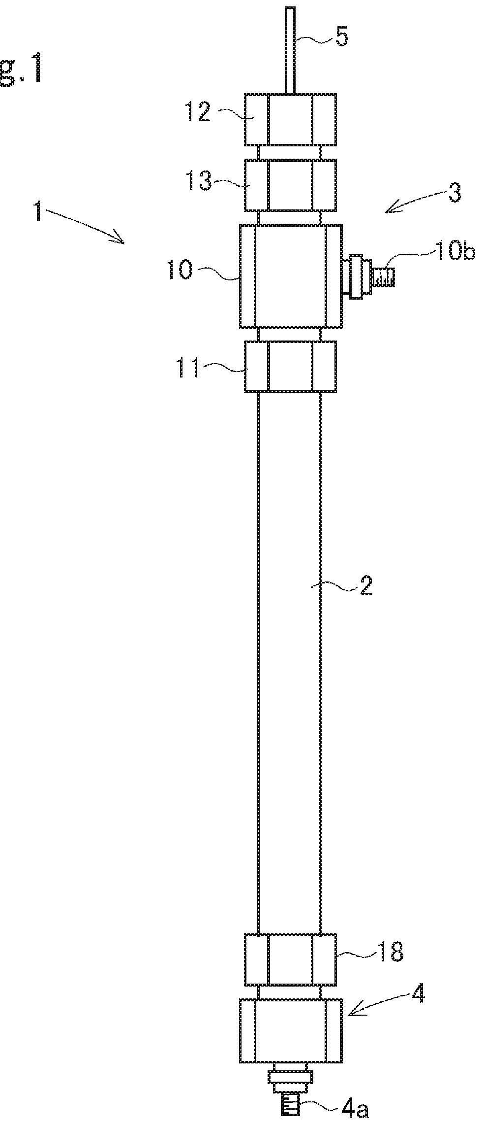
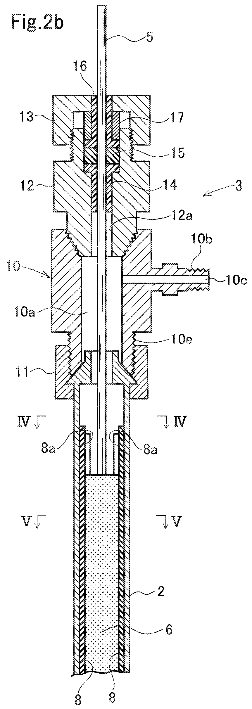
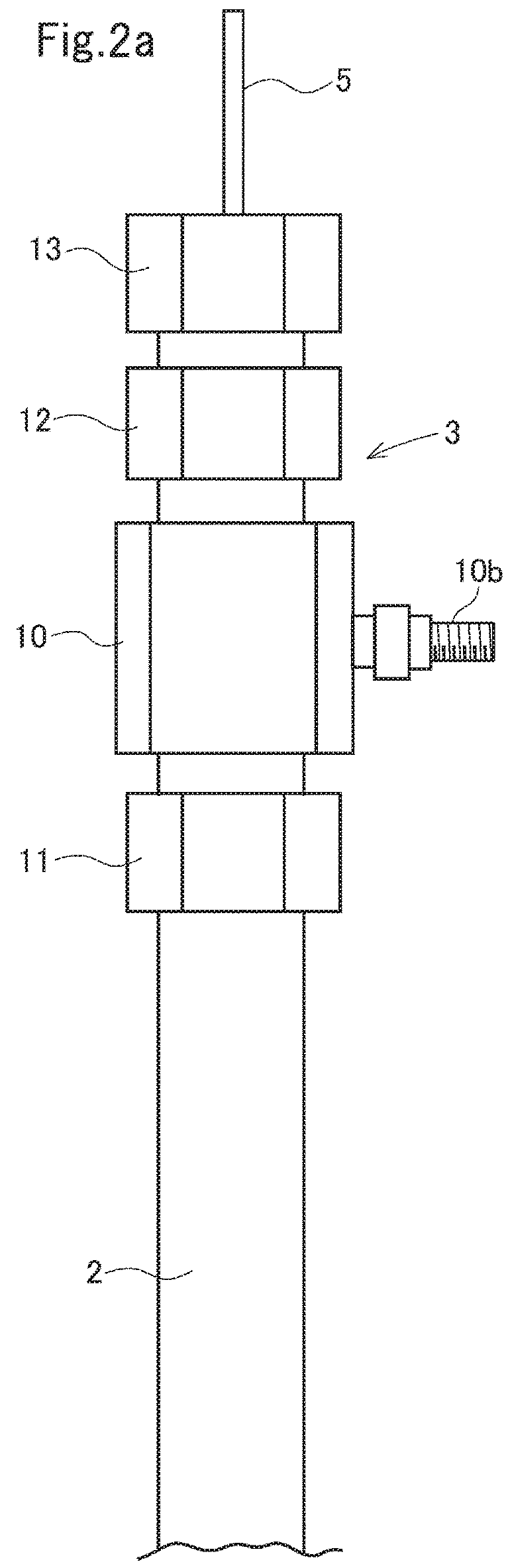
[0117]The electrolysis apparatus used in Example 2 was replaced with an electrolysis apparatus having the same structure as in FIGS. 1 to 5 except that the insulators were omitted, which included the anode plate 6 and the bipolar electrode plates 7. Specifically, the electrolysis apparatus used included an iridium oxide electrode serving an anode plate and two conductive diamond electrodes serving as bipolar electrodes, the conductive diamond electrodes having the same dimensions as the anode plate and being arranged on the respective sides of the iridium oxide electrode so as to be parallel to the anode plate at intervals of 1 mm. An electrolysis treatment was performed as in Example 2 except the above change was made. FIG. 20 illustrates the results. FIG. 20 also illustrates the results obtained in Example 1.

[0118]As is clear from the results shown in FIG. 20, the amount of current required for reducing the TOC concentration to 10 mg / L or less was 58 Ah / L in Example 3 where the el...


PUM

PropertyMeasurementUnit
diameteraaaaaaaaaa
diameteraaaaaaaaaa
concentrationaaaaaaaaaa

Abstract

Provided is an electrolysis apparatus with which the liquid that is to be treated can be continuously electrolyzed with high efficiency under high-temperature and high-pressure conditions. The electrolysis apparatus includes a cylindrical container main body including an inner peripheral surface serving as a cathode surface, an anode plate disposed in the container main body along an axis thereof, and end members attached to the respective ends of the container main body with nuts interposed therebetween, respectively. The end members are provided with nozzles, respectively, through which the liquid is passed. The end member is provided with a power supply rod connected to the anode plate which is inserted in the end member. Bipolar electrode plates are disposed in the container main body so as to be parallel to the anode plate. Insulators support the sides of the anode plate and the sides of the bipolar electrode plates.

Description

TECHNICAL FIELD[0001]The present invention relates to an apparatus and method for electrolyzing reducing substances contained in water under high-temperature and high-pressure conditions. The present invention relates specifically to the electrolysis apparatus with which a liquid that is to be treated and contains reducing substances, such as organic substances and ammonia (e.g., organic liquid waste and various types of industrial liquid waste that contain halide ions) can be continuously electrolyzed with a high current efficiency. The present invention further relates to the water treatment method in which the electrolysis apparatus is used.BACKGROUND ART[0002]Hydrothermal electrolysis apparatuses that oxidatively decompose reducing substances, such as organic substances (including synthetic polymers) and ammonia, by performing electrolysis under high-temperature and high-pressure conditions to cause hydrothermal reaction simultaneously are known (Patent Literature (PTL) 1 to PTL...

Claims


Application Information

Patent Timeline
Patent Type & Authority Applications(United States)
IPC IPC(8): C02F1/461
CPCC02F1/46109C02F2001/46128C02F2001/46147C02F2001/46152C02F1/025C02F1/46104C02F1/4672C02F2001/46171C02F2101/30C02F2201/4611C02F2301/066
Inventor MATSUMOTO, YUKITAKAKOBAYASHI, HIDEKI
Owner KURITA WATER INDUSTRIES LTD
Why Eureka
Try Eureka