Turbine stator vane and/or turbine rotor vane with a cooling flow adjustment feature and corresponding method of adapting a vane

a technology of cooling flow and turbine stator, which is applied in the direction of engine fuction, machine/engine, engine manufacturing, etc., can solve the problems of reducing the energy level of the engine, different firing temperatures and/or different life requirements, and loss of performance, so as to optimize the cooling flow and maximize the overall efficiency of the engine.

Active Publication Date: 2018-06-28
SIEMENS ENERGY GLOBAL GMBH & CO KG
View PDF4 Cites 2 Cited by
  • Summary
  • Abstract
  • Description
  • Claims
  • Application Information

AI Technical Summary

Benefits of technology

[0043]For example, at least during the supplying the cooling fluid through the channel by varying the setting value and during the measuring of the observation value and comparing the observation value to the target value, the vane may be mounted in the target turbine. Thus, the optimization may be closely tied to the later field of application, thus guaranteeing a precise optimization of the cooling flow.
[0044]Accordingly, an engine overall efficiency may be maximized while thermal requirements are met.

Problems solved by technology

Further, the same type of vane may be used in different types or versions of turbines, and further in different fields of operation, which may result in different firing temperatures and / or different life requirements.
This, however, results in a loss of performance, since on the one hand cooling fluid and in particular cooling air mixes, when leaving the turbine vane, to the hot gas in the turbine and thus reduces its energy level.

Method used


Image

  • Turbine stator vane and/or turbine rotor vane with a cooling  flow adjustment feature and corresponding method of adapting a  vane
  • Turbine stator vane and/or turbine rotor vane with a cooling  flow adjustment feature and corresponding method of adapting a  vane
  • Turbine stator vane and/or turbine rotor vane with a cooling  flow adjustment feature and corresponding method of adapting a  vane

Examples


third embodiment

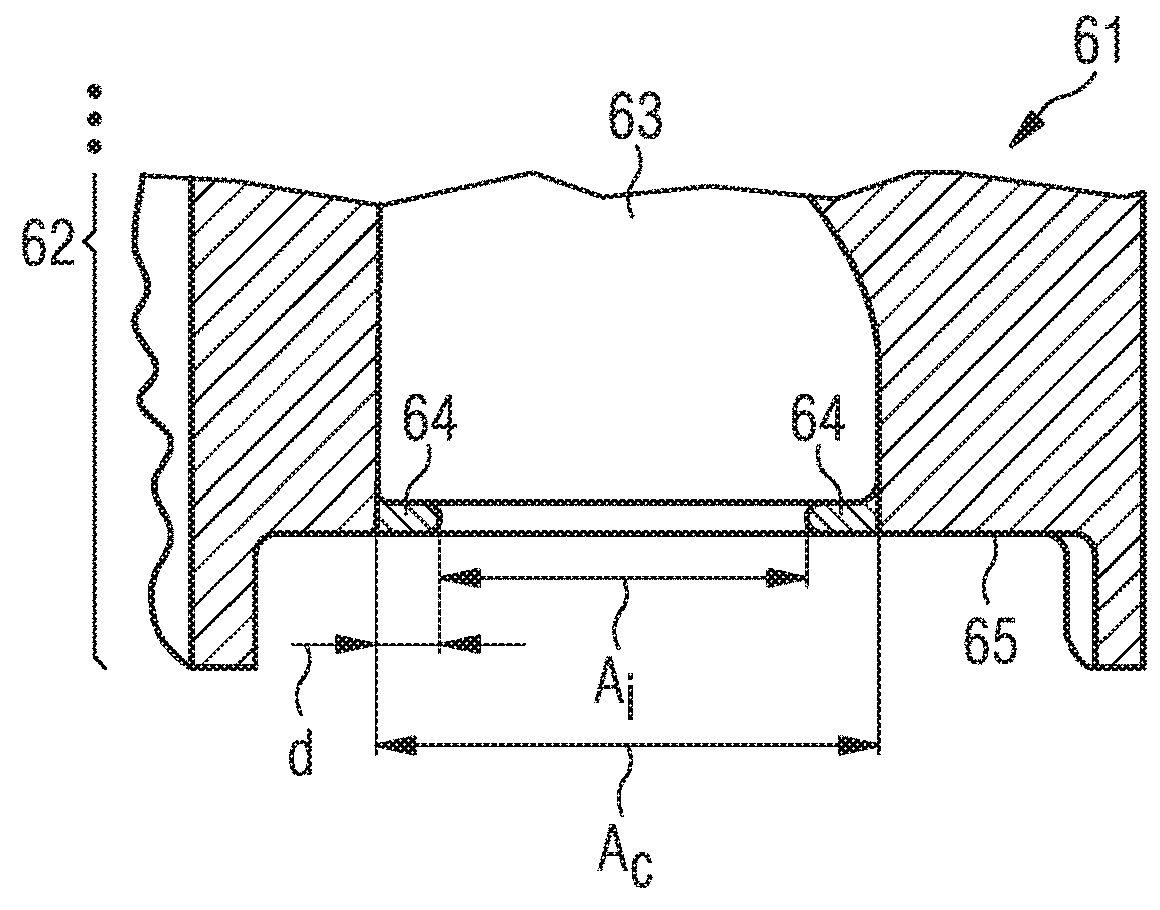
[0072]In FIG. 5 is a similar view to FIG. 4 and shows the flow adaption feature 64. However, here the flow adaption feature 64 does not have a constant extent d into the cooling channel and forming the inlet opening 73. At the forward part or left hand side the flow adaption feature 64 has a greater extent d2 than elsewhere indicated by d1.

fourth embodiment

[0073]FIG. 6 is a similar view to FIG. 4 and shows the flow adaption feature 64. However, the flow adaption feature 64 does not have a constant extent d into the aperture formed by the inlet opening 73. Instead there are two separate sections to the flow adaption feature indicated by 64a and 64b. Here the generally oval cooling channel 76 has an inlet opening 73 formed partly by the channel 76 itself and partly by the fore and aft flow adaption feature regions 64a, 64b. The fore flow adaption feature 64a is show on the left hand side of the figure. The fore and aft flow adaption features 64a, 64b need not be the same size and nor do they necessarily require the same machining when the inlet area Ai is increased.

[0074]In FIG. 7, an embodiment of a method for adapting a vane, e.g. vane 1, is illustrated. The method has optional steps, illustrated by dashed rectangles, and a mandatory step, illustrated by a continuous rectangle.

[0075]After a beginning 6 of the method, a target turbine ...


PUM


Abstract

A turbine stator vane or turbine rotor vane has a body, a channel being adapted for leading a cooling fluid through the body, and a flow adaption feature protruding from the body to the channel in such a manner as to reduce a cross-sectional area of the channel.

Description

CROSS REFERENCE TO RELATED APPLICATIONS[0001]This application is the US National Stage of International Application No. PCT / EP2016 / 065954 filed Jul. 6, 2016, and claims the benefit thereof. The International Application claims the benefit of European Application No. EP15175475 filed Jul. 6, 2015. All of the applications are incorporated by reference herein in their entirety.FIELD OF INVENTION[0002]The invention relates to a cooling adjustment feature for turbine stator and / or rotor vanes, for example blades or vanes of a steam or gas turbine.BACKGROUND OF INVENTION[0003]Turbine vanes, such as turbine stator vanes or rotor vanes, the latter being also known as turbine blades, are subjected during operation in a gas or steam turbine to hot gas or steam. Thus, they need an active cooling, which is achieved by passing a cooling fluid such as air through internal passages of the vanes known as cooling channels.[0004]The pressure drop and flow-rate of the cooling fluid is determined inter...

Claims


Application Information

Patent Timeline
Patent Type & Authority Applications(United States)
IPC IPC(8): F01D5/18F01D9/04F01D25/12
CPCF01D5/18F01D9/041F01D25/12F05D2250/512F05D2230/10F05D2260/20F05D2240/12F05D2260/83F05D2230/21F05D2230/22F05D2230/30F01D9/06F01D5/10
Inventor BATT, STEPHEN
Owner SIEMENS ENERGY GLOBAL GMBH & CO KG
Why Eureka
Try Eureka