[0015]If scaling the samples for the amplitude is simpler than attenuating the feedback signal in very fine steps, a combination of both methods also can be used. Attenuation is then performed in a few coarse steps in accordance with the present invention and, in conjunction with this, the samples for the amplitude are scaled into a smaller range for the fine adjustment. This also considerably limits the
dynamic range in the feedback
branch but provides for very fine adjustment in a fairly simple way.
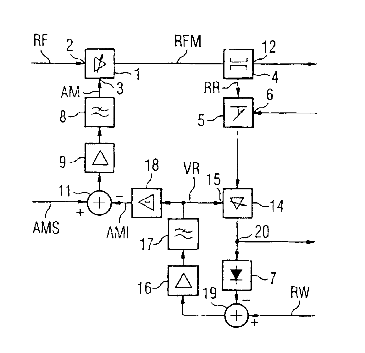
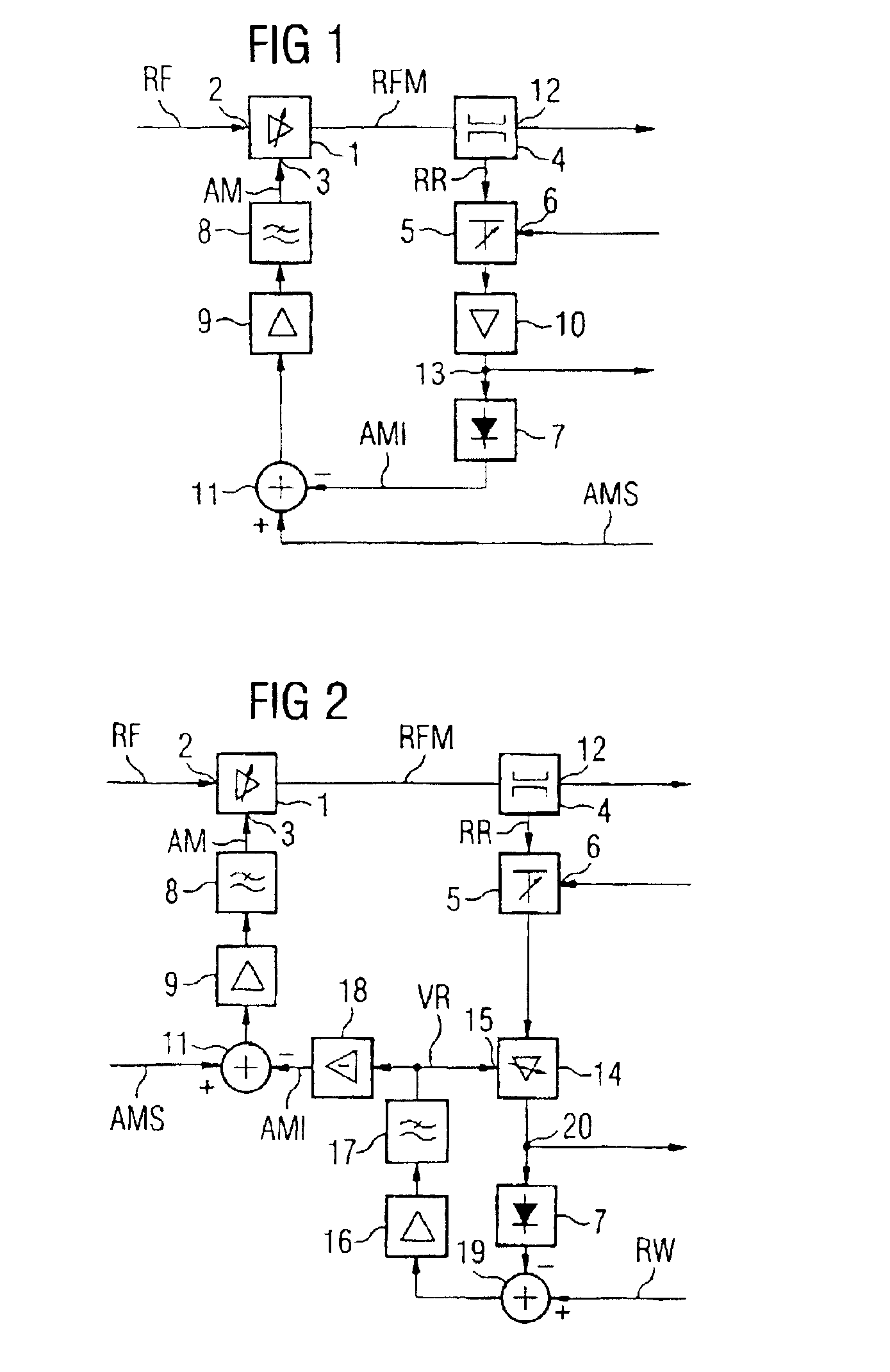
[0019]In a further preferred exemplary embodiment, the feedback signal, attenuated in accordance with the mean transmission power, is supplied to a controllable
amplifier which regulates the amplitude of the feedback signal to a fixed value which can be predetermined by a reference value, in a further control loop. This method is possible whenever modulation types are used in which the amplitude does not become zero. This requires an amplifier, which can be controlled within the restricted
dynamic range, with a sufficiently
linear relationship between the logarithm of the amplification and the control
voltage. The control
voltage within the second control loop for the controllable amplifier is then negatively proportional to the logarithm of the output amplitude of the transmission amplifier and can be used as actual value in the control loop for the transmission amplifier. Such a circuit further reduces, in particular, the requirements for the
envelope detector which is now located behind the controllable amplifier within the control loop. In addition, a signal which is no longer amplitude modulated at all is available as actual signal for a control loop, which may be additionally needed, for the phase-modulated signal.
[0020]To generate a transmission signal with
high transmission power during the generation of an amplitude-modulated and phase-modulated transmission signal, as is required, for example, in current
mobile radio standards, with the best possible
linearity of the transmission amplifier, it is generally known to the expert to split the signal to be transmitted in accordance with amplitude and phase and only to apply the signal carrying the
phase modulation (i.e., a phase-modulated input signal), to the signal input of the transmission amplifier and to impress the
amplitude modulation signal onto the phase-modulated input signal via the transmission amplifier via at least one further input; for example, the input for the supply
voltage or an input for the
transistor bias voltage. Attention is paid to the fact that the phase-modulated input signal and the amplitude modulation signal are applied matching one another in time in such a manner that the original signal shape is produced again. This method is currently used for amplifying amplitude-modulated and phase-modulated signals which already have been combined. From the amplitude-and phase-modulated signal, the envelope curve, or the amplitude information, is first removed and the signals are applied separately and as described to the transmission amplifier so that the total signal is restored there. The method is, therefore, also generally called “Envelope
Elimination and Restoration” (EER). The method has the
advantage that the phase-modulated input signal has a constant amplitude and the efficiency of the transmission amplifier can be optimized accurately to this amplitude and can be operated, for example, in saturation. The amplitude modulation signal can be suitably amplified separately so that overall very high efficiency can be achieved. Naturally, this presupposes that the amplitude modulation signal (i.e., the fluctuating supply voltage or bias voltage of the transmission amplifier), in turn, can be generated with good efficiency and good
linearity and thus a pure and sufficiently
high amplitude modulation signal is present.
[0027]Thus, a sufficiently pure transmission signal is achieved with a given transmission power level. When the transmission power level changes, this correction amplification is preferably adapted. As an alternative, the slope at an
instantaneous amplitude or the slope at the location of a mean value of the amplitude also can be used instead of the slope at the point of the required mean transmission power, and the temporal determination can be made over a relatively short or long time. The period of the determination also can depend on how long the amplitude stays in an area in which the non-linear function of the control loop or of the transmission amplifier can be linearized with sufficient accuracy for the output signal.
[0029]Such a method of linearizing the non-linear function of the control loop area by area or section by section meets in a simple manner the requirements for the stability,
frequency response and group
delay of the closed control loop for, in each case, one mean transmission power set. That is to say, correction amplification does not need to be carried out in the
rhythm of the amplitude modulation in the case of a moderate
modulation index and moderate
linearity. This method also can, therefore, be used generally in other control loops for amplitude modulation, independently of the concept of attenuation of the feedback signal according to the present invention. It is, therefore, an independent inventive concept.
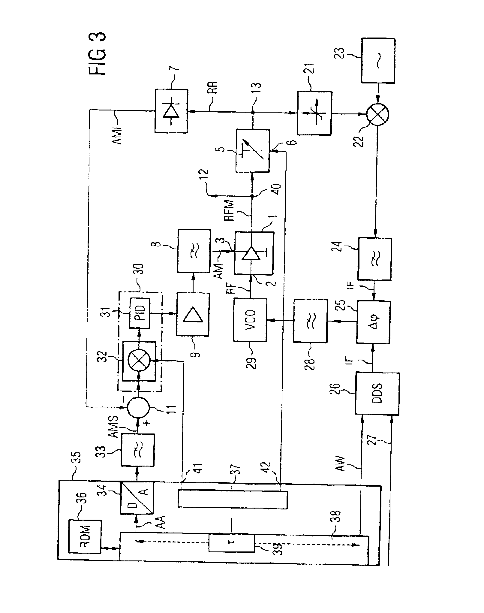
[0032]In principle, these components for correction can be arranged at any point in the control loop. However, if the method according to the present invention is used such that the transmission power level is adjusted by adjustable attenuation and / or amplification in the feedback signal, so that the nominal signal is independent of the transmission power level, an adjustment of the correction amplification or of the correction parameters between the
comparator and the output stage is appropriate in order to scale the signals in the forward
branch in accordance with the transmission output stage. Correction amplification in the forward
branch has the
advantage that the
loop gain is kept constant. If the attenuation in the feedback is thus increased, such as by 1 dB, the
gain in the forward branch should be higher by 1 dB with a linear characteristic.

