Optimization of beam utilization

Inactive Publication Date: 2006-06-01
AXCELIS TECHNOLOGIES
View PDF4 Cites 22 Cited by
  • Summary
  • Abstract
  • Description
  • Claims
  • Application Information

AI Technical Summary

Benefits of technology

[0011] According to another exemplary aspect, the ion beam profile is determined based on one or more of empirical data associated with an ion implantation and a predicti

Problems solved by technology

Processing batches of substrates in such a manner, however, generally makes the ion implanter substantially large in size.
The process of scanning or shaping a uniform ion beam, however, generally requires a complex and/or long beam line, which is generally undesirable at low energies.
However, such a uniform

Method used


Image

  • Optimization of beam utilization
  • Optimization of beam utilization
  • Optimization of beam utilization

Examples


Embodiment Construction

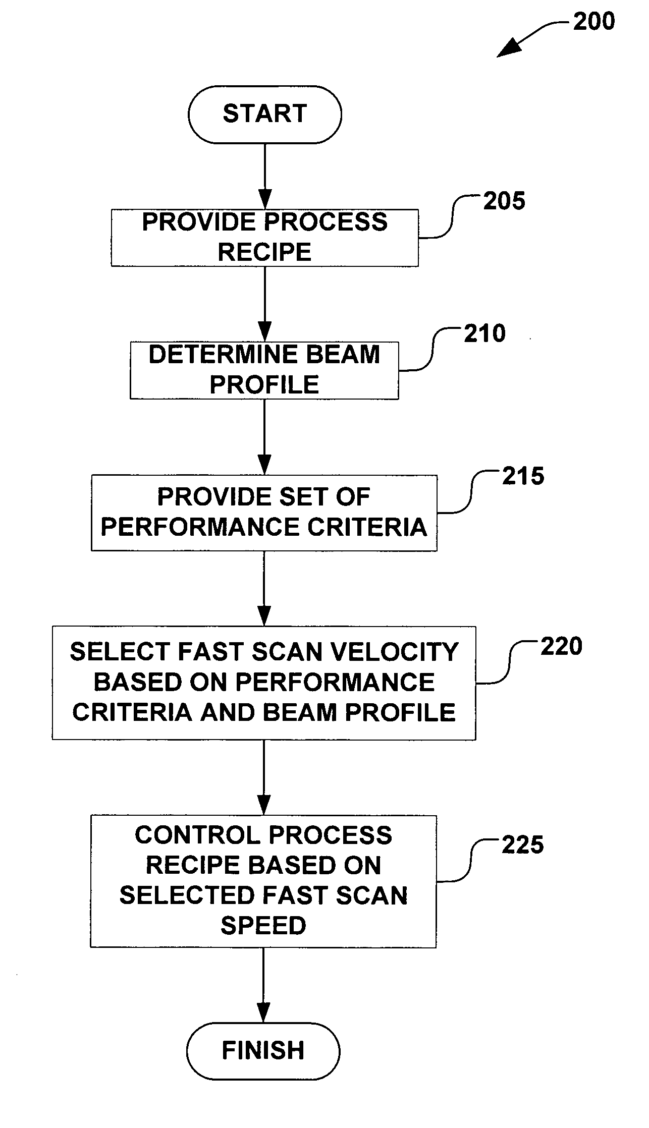
[0018] The present invention is directed generally towards a method for optimizing an ion beam utilization efficiency when scanning a substrate relative to an ion beam in an ion implantation system. More particularly, the method provides an optimization based on one or more performance criteria associated with the ion implantation system. Accordingly, the present invention will now be described with reference to the drawings, wherein like reference numerals are used to refer to like elements throughout. It should be understood that the description of these aspects are merely illustrative and that they should not be taken in a limiting sense. In the following description, for purposes of explanation, numerous specific details are set forth in order to provide a thorough understanding of the present invention. It will be evident to one skilled in the art, however, that the present invention may be practiced without these specific details.

[0019] Productivity in ion implantation system...


PUM


Abstract

A method for optimizing an ion implantation, wherein a substrate is scanned in two dimensions through an ion beam. The method provides a process recipe comprising one or more of a current of an ion beam, a dosage of ions, and a number of substrate passes through the beam in a slow scan direction. The beam is profiled based on the process recipe, and a size of the beam is determined. One of a plurality of differing scan speeds in a fast scan direction is selected, based on a desired uniformity of the implantation and the process recipe. The process recipe is controlled, based on one or more of the desired uniformity, a throughput time for the substrate, a desired minimum ion beam current, and one or more substrate conditions. One of a plurality of speeds in a slow scan direction is selected, based on the dosage of the implantation.

Description

FIELD OF THE INVENTION [0001] The present invention relates generally to semiconductor processing systems, and more specifically to a method for optimizing a utilization of an ion beam associated with an ion implantation of a semiconductor substrate. BACKGROUND OF THE INVENTION [0002] In the semiconductor industry, various manufacturing processes are typically carried out on a substrate (e.g., a semiconductor wafer) in order to achieve various results on the substrate. Processes such as ion implantation, for example, can be performed in order to obtain a particular characteristic on or within the substrate, such as limiting a diffusivity of a dielectric layer on the substrate by implanting a specific type of ion. Conventionally, ion implantation processes are performed in either a batch process, wherein multiple substrates are processed simultaneously, or in a serial process, wherein a single substrate is individually processed. Traditional high-energy or high-current batch ion impl...

Claims


Application Information

Patent Timeline
IPC IPC(8): H01J37/08
CPCH01J37/3023H01J37/3171H01J2237/20228H01J2237/20285H01J2237/30411H01L21/265
Inventor RAY, ANDREWGRAF, MICHAEL
Owner AXCELIS TECHNOLOGIES
Why Eureka
Try Eureka