Road surface sensor and monitoring control method for road surface

a technology of road surface and sensor, which is applied in the direction of roads, roads, instruments, etc., can solve the problems of conventional snow-melting apparatus, etc., and achieve the effect of not wasting energy and consuming energy

Inactive Publication Date: 2005-03-03
YAMADA TECH CORP +1
View PDF10 Cites 30 Cited by
  • Summary
  • Abstract
  • Description
  • Claims
  • Application Information

AI Technical Summary

Benefits of technology

[0017] The conventional snow-melting apparatus has problems as described above. The invention intends to solve these problems and it is an object of the invention to provide a road surface sensor that can measure a road surface state seque

Problems solved by technology

The conventional snow-melting appara

Method used


Image

  • Road surface sensor and monitoring control method for road surface
  • Road surface sensor and monitoring control method for road surface
  • Road surface sensor and monitoring control method for road surface

Examples


Embodiment Construction

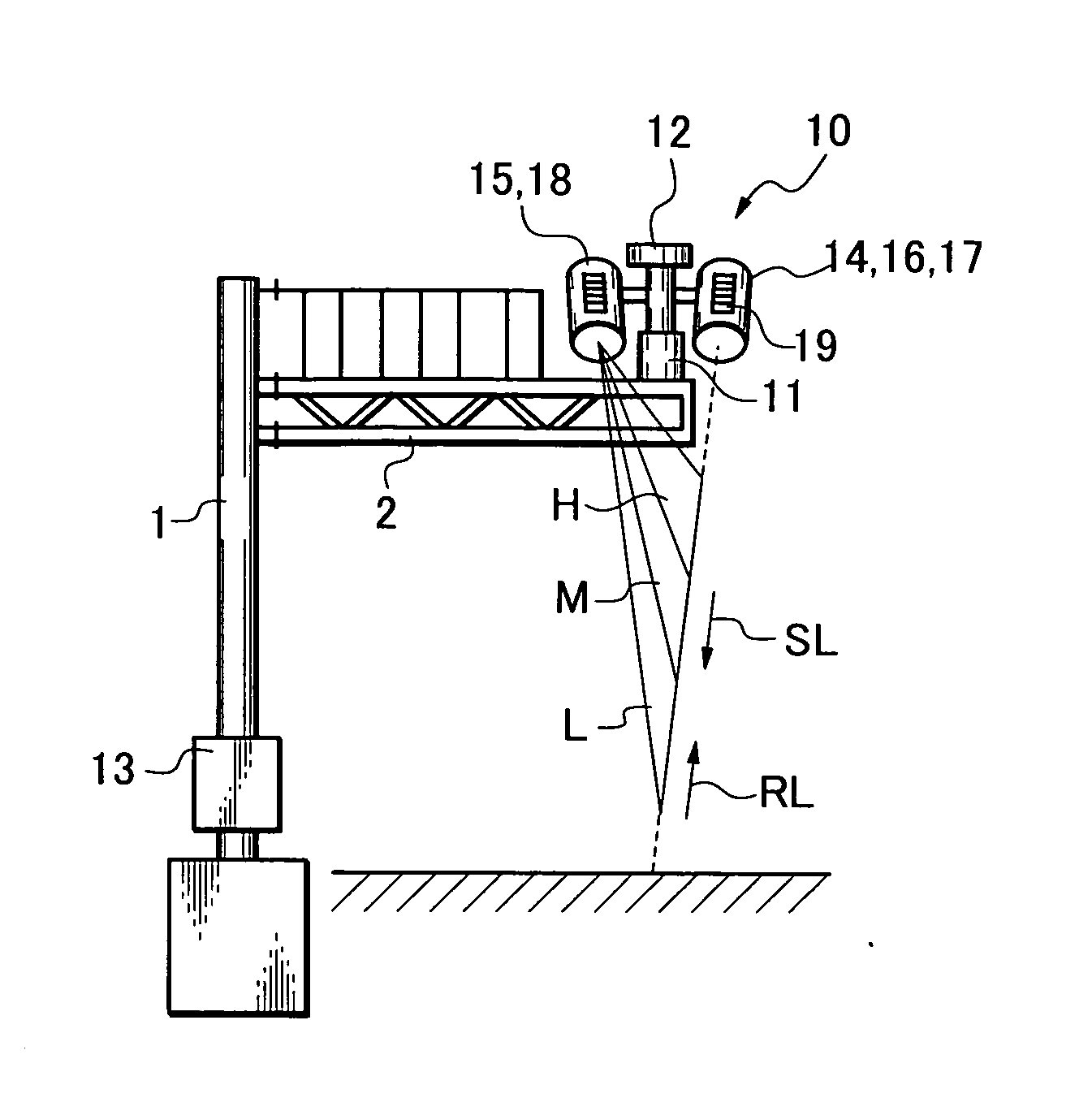
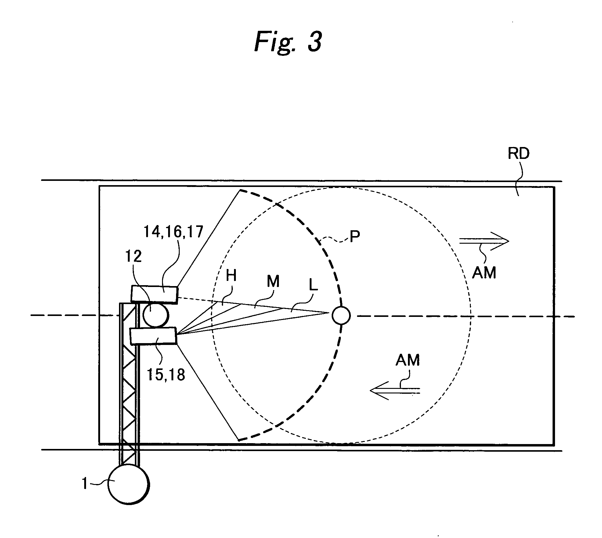
[0059]FIG. 1 shows an embodiment of a road surface sensor in accordance with the invention. A road surface sensor 10 is set on a tip portion of a support arm 2 that sticks out horizontally toward the center of a road from a place equal to or higher than 5.5 meters of a support pole 1 provided on a road shoulder. The road surface sensor 10 includes a rotating stand 11 attached on the support arm 2 so as to be reciprocatingly rotatable horizontally in a range of 330 degrees, a group of sensors that are attached to the rotating stand 11, and a signal converter 13 attached to a lower part of the support pole 1. The group of sensors include a snow-melting / freezing heat quantity measurement dummy road surface 12 attached to a head of the rotating stand 11, a reference light irradiating / reflected light receiving device 14, a space reflection receiving device 15, a non-contact road temperature measuring device 16, a non-contact snow cover depth measuring device 17, a road surface image pick...


PUM


Abstract

In order to melt snow and prevent freezing without consuming energy wastefully and to monitor a road surface state remotely, a road surface sensor includes: a rotating stand provided so as to be reciprocatingly rotatable upward on the road surface; a snow-melting/freezing heat quantity measurement dummy road surface having an electric heater buried therein and to use as a reference road surface for heat quantity measurement to derive a melting heat quantity for snow falling on the surface and a heat quantity required for freezing prevention; a reference light irradiating/reflected light receiving device that is attached so as to be rotatable with the rotating stand; a space reflected light receiving device; a non-contact road temperature measuring device; a non-contact snow cover depth measuring device; a road surface image pickup device; and a moisture sensor. The reference light irradiating/reflected light receiving device includes a reference light irradiating device for irradiating reference light and a reflected light receiving device for receiving reflected light of the reference light from the road surface, and the reflected light receiving device separates and receives only reflected light of the reference light out of the reflected light from the road surface.

Description

BACKGROUND OF THE INVENTION [0001] 1. Field of the Invention [0002] The present invention relates to a road surface sensor that can confirm a state of weather / road surface / control in a remote location while performing automatic control for road snow-melting by measuring a snowfall and an amount of freezing as a heat quantity required for snow-melting and a heat quantity required for freezing prevention in a unit time period, measuring a state of distribution of drying, wetting, snow cover, snow cover depth, and temperature on a road surface transversely in a non-contact manner, and combining the measured heat quantities and the state of road surface, and a method for control for snow-melting and remote monitoring control using the road surface sensor. [0003] 2. Related Art [0004] There are various types of snow-melting facilities, which are indispensable for life and industrial activities in snow-covered cold regions. In particular, whereas the snow-melting facilities contribute to ...

Claims


Application Information

Patent Timeline
IPC IPC(8): E01C23/07E01C11/26G01N21/17G01N21/47G01W1/00G01W1/14G08B19/02
CPCG08B19/02G01W1/14
Inventor YAMADA, TADAYUKIYAMAMOTO, KOUJIGOTO, MAKOTO
Owner YAMADA TECH CORP
Why Eureka
Try Eureka