Shaped ground plane for dynamically reconfigurable aperture coupled antenna

Inactive Publication Date: 2005-03-03
HARRIS CORP
View PDF9 Cites 84 Cited by
  • Summary
  • Abstract
  • Description
  • Claims
  • Application Information

AI Technical Summary

Benefits of technology

[0008] The invention concerns a method for controlling an input impedance of an antenna by varying a shape of a ground plane. The method includes the steps of coupling RF energy from an input RF transmission line to an antenna radiating element through an aperture defined in the ground plane. The input impedance is controlled by selectively varying at least one dimension of the aperture in response to a control signal. The step of varying the dimension of the aperture can further comprise varying the volume and/or the position of a conductive fluid. According to one aspect of the invention, the ra

Problems solved by technology

One negative aspect of patch antennas is that they usually have a relatively narrow impedance bandwidth.
Patch antennas that are fed with an aperture or slot can have slightly higher bandwidths, in the range from about 4% to 6%, but th

Method used


Image

  • Shaped ground plane for dynamically reconfigurable aperture coupled antenna
  • Shaped ground plane for dynamically reconfigurable aperture coupled antenna
  • Shaped ground plane for dynamically reconfigurable aperture coupled antenna

Examples


Embodiment Construction

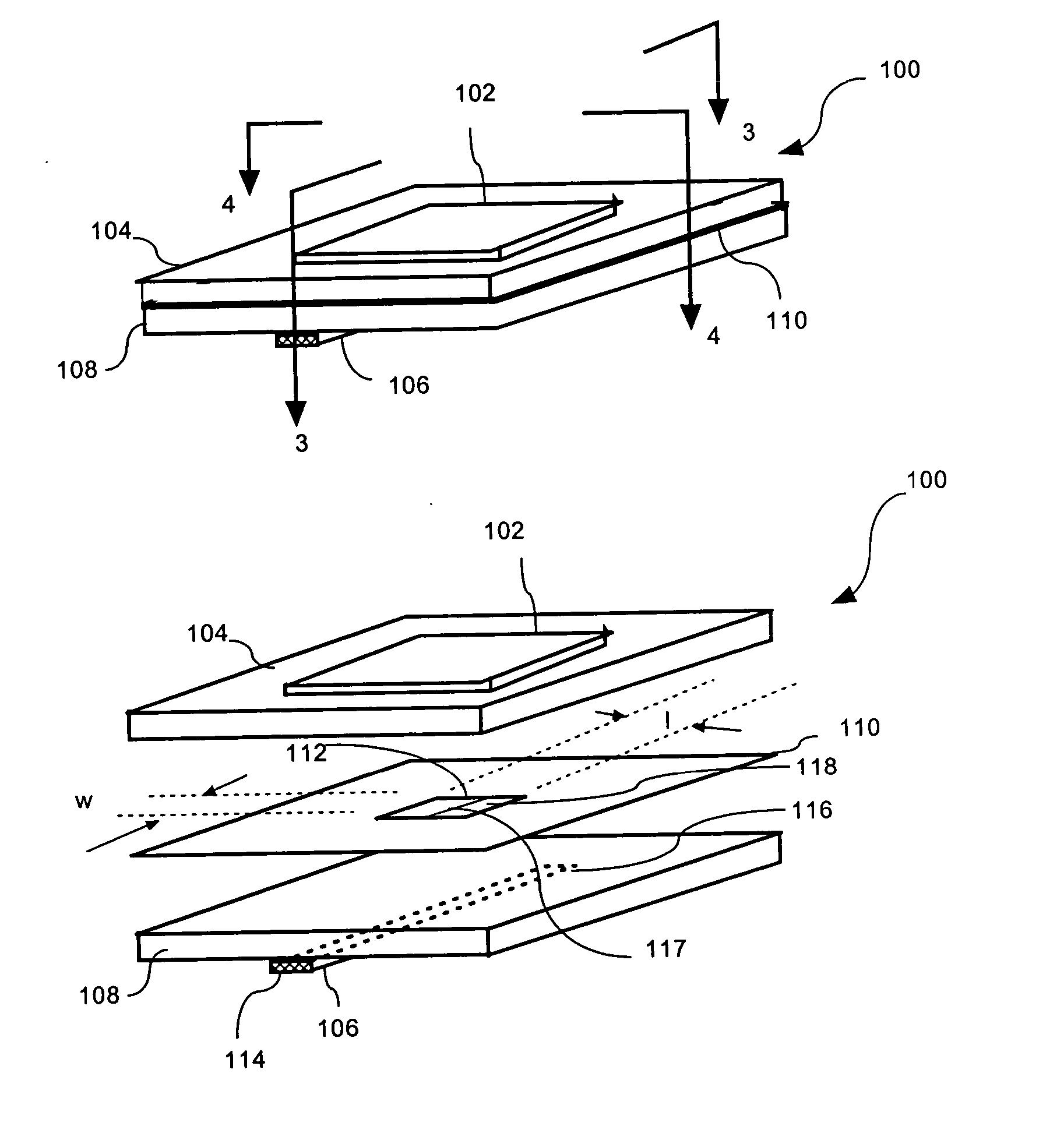
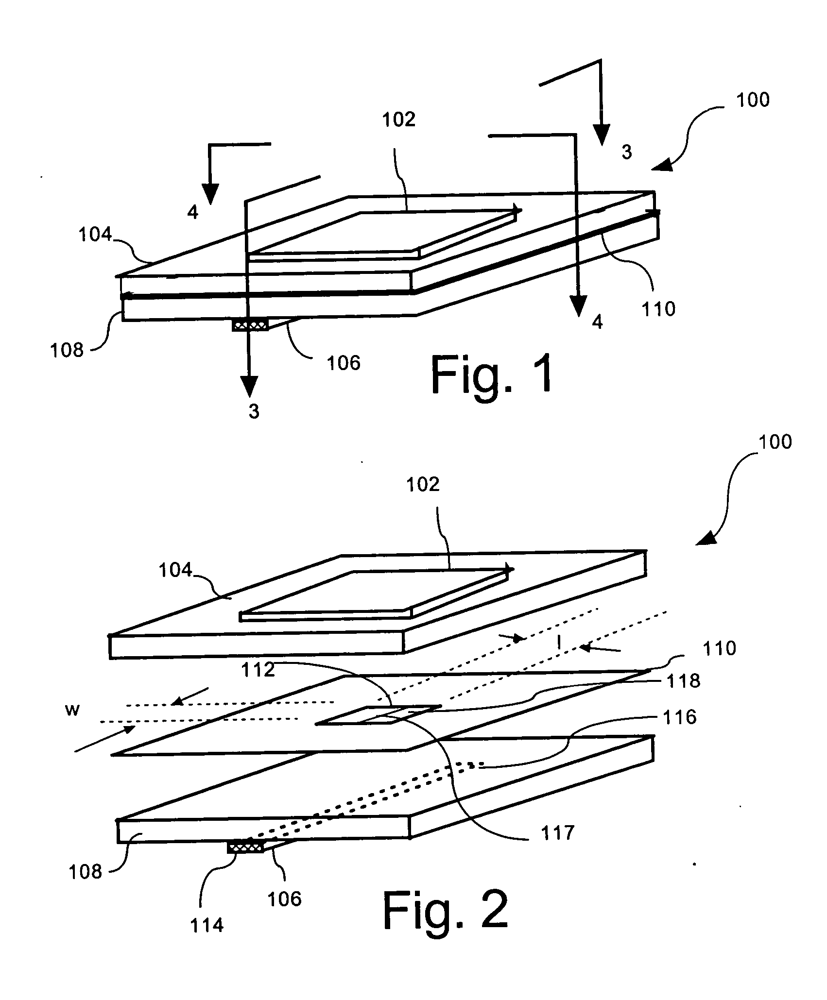
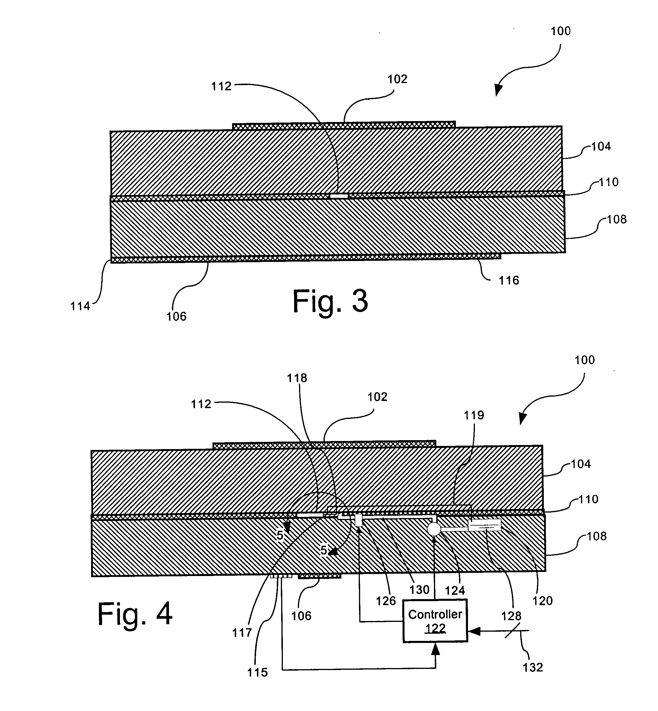
[0021]FIG. 1 is a perspective view of an aperture-fed patch antenna 100 that is useful for understanding the invention. The antenna is comprised of a radiating element 102 disposed on a dielectric antenna substrate 104. The radiating element 102 in FIG. 1 is shown as having a rectangular geometry as is common for patch type antennas, but it should be understood that the invention is not so limited. Instead, the radiating element 102 can have any of a wide variety of geometric designs as would be known to those skilled in the art.

[0022] A feed line 106 can be disposed on a surface of the antenna 100 opposed from the radiating element 102. According to a preferred embodiment, the feed line 106 can be a microstrip transmission line as shown. However, the invention is not limited in this regard and other arrangements are also possible. For example, feed line 106 could also be arranged in a buried microstrip or stripline configuration.

[0023] As illustrated in FIGS. 1 and 2, the feed li...


PUM


Abstract

Method for controlling an input impedance of an antenna (100). The method can include the steps of coupling RF energy from an input RF transmission line (106) to an antenna radiating element (102) through an aperture (112) defined in a ground plane (110). For example, the aperture (112) can be a slot and the radiating element (102) can be a patch type element. The input impedance can thereafter be controlled by selectively varying a volume or a position of a conductive fluid (128) disposed in a predetermined region between the RF transmission line and the antenna radiating element. The volume of conductive fluid (128) can be automatically varied in response to at least one control signal (132).

Description

BACKGROUND OF THE INVENTION [0001] 1. Statement of the Technical Field [0002] The invention concerns antennas and more particularly aperture coupled antennas that can be dynamically modified to operate over a relatively large bandwidth by controlling a shape of a ground plane. [0003] 2. Description of the Related Art [0004] Patch antennas are well known in the art and are used in a wide variety of applications. They can be manufactured in a nearly unlimited number of shapes and sizes, and can be made to conform to most surface profiles. Patch antennas also possess an omni-directional radiation pattern that is desirable for many uses. [0005] One negative aspect of patch antennas is that they usually have a relatively narrow impedance bandwidth. For a typical classically fed patch antenna, bandwidth is usually about 2% to 3%. Patch antennas that are fed with an aperture or slot can have slightly higher bandwidths, in the range from about 4% to 6%, but this is still too narrow for many...

Claims


Application Information

Patent Timeline
IPC IPC(8): H01Q9/04
CPCH01Q9/0457H01Q9/0442
Inventor RAWNICK, JAMES J.DURHAM, TIMOTHY E.BROWN, STEPHEN B.
Owner HARRIS CORP
Why Eureka
Try Eureka