

Flexible photoinduced ultrasonic thin film transducer and preparation method thereof
A technology of photoinduced ultrasound and transducers, applied in the direction of fluid using vibration, etc., can solve problems such as ultrasonic loss and poor coupling, and achieve the effects of reducing ultrasonic loss, widening resolution, and increasing frequency bandwidth
- Summary
- Abstract
- Description
- Claims
- Application Information
AI Technical Summary
Problems solved by technology
Method used
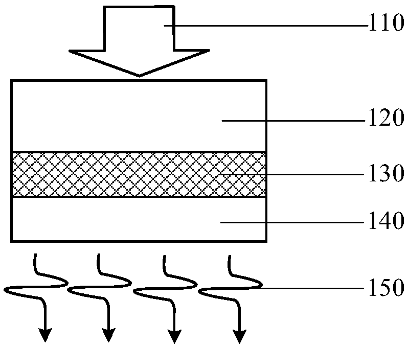
Image

Examples
Embodiment 1
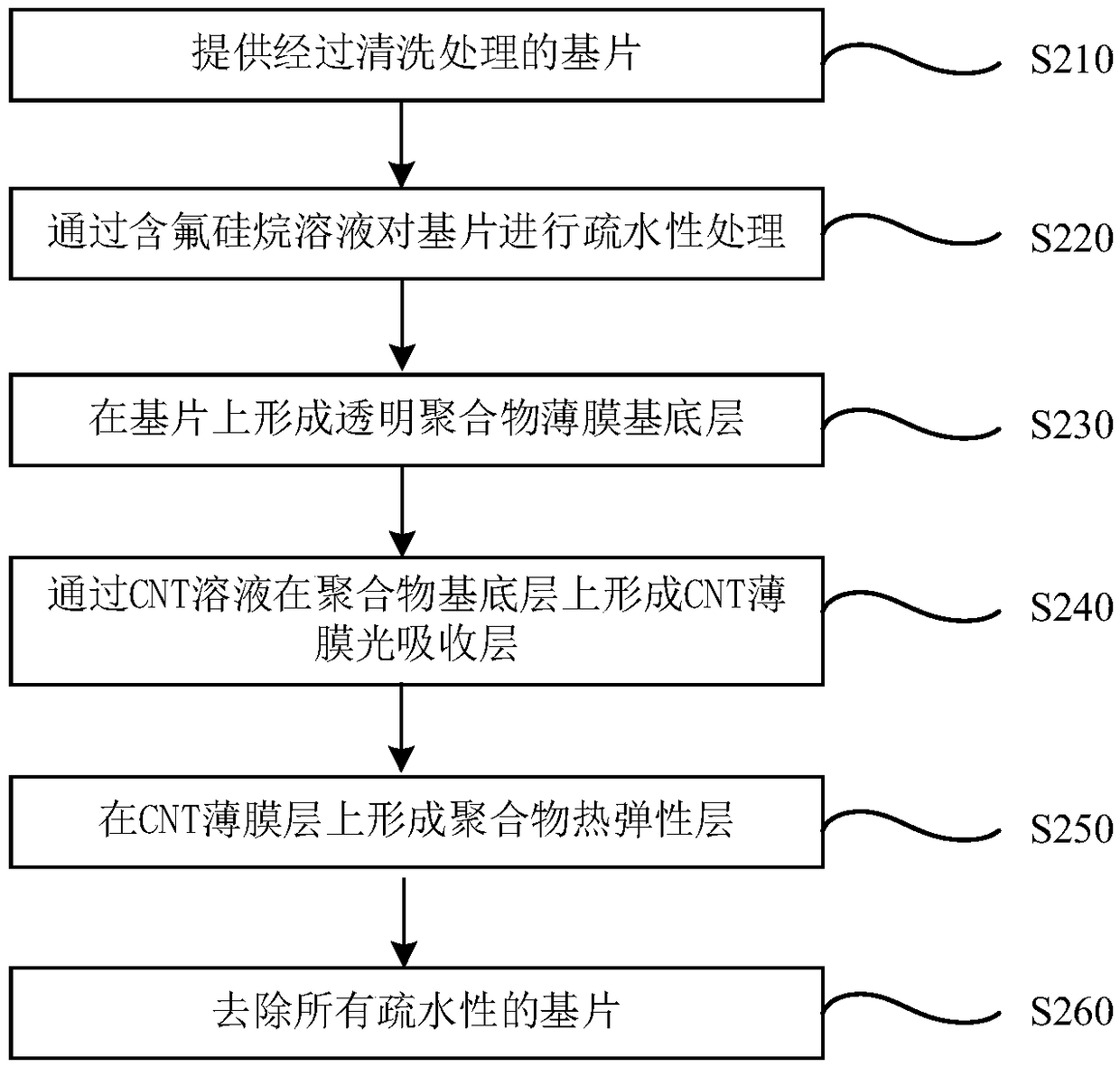
[0048] Such as figure 2 As shown, the steps of the present invention to prepare the flexible photo-ultrasonic thin film transducer Example 1 are as follows.
[0049] 1. Step S210, providing a cleaned glass substrate.
[0050] The glass substrate is treated with vacuum plasma to remove organic impurities on the glass surface and increase surface wettability. The substrate provided in this step can be but not limited to glass.
[0051] Among them, the vacuum plasma treatment time is 300s.
[0052] 2. Step S220, using a fluorine-containing silane solution to perform hydrophobic treatment on the substrate.
[0053] Soak the substrate cleaned in step S210 in the fluorine-containing silane solution, take out the substrate after a period of time, and then rinse and dry it. It is also possible to form a substrate with a hydrophobic surface based on a fluorine-containing silane solution and using methods such as spin coating, solution spraying, solution evaporation, and the like. ...
Embodiment 2
[0068] 1. Step S210, providing a cleaned glass substrate.
[0069] The supplied substrates are vacuum plasma treated to remove organic impurities from the glass surface and increase surface wettability. The substrate provided in this step can be but not limited to glass.
[0070] Among them, the vacuum plasma treatment time is 300s.
[0071] 2. Step S220, using a fluorine-containing silane solution to perform hydrophobic treatment on the substrate.
[0072] Soak the substrate cleaned in step S210 in the fluorine-containing silane solution, take out the substrate after a period of time, and then rinse and dry it. It is also possible to form a substrate with a hydrophobic surface based on a fluorine-containing silane solution and using methods such as spin coating, solution spraying, solution evaporation, and the like.
[0073] The fluorine-containing silane solution in this embodiment is a mixed solution of tridecafluorooctyltrimethoxysilane and toluene, and the concentratio...
Embodiment 3
[0086] The fluorine-containing silane solution used in this embodiment is a mixture of dodecafluoroheptylpropyltrimethoxysilane and toluene, wherein the concentration of fluorine-containing silane is 10 vol%.
[0087] Specifically, the steps are as follows:
[0088] 1. Step S210, providing a cleaned glass substrate.
[0089] The supplied substrates are vacuum plasma treated to remove organic impurities from the glass surface and increase surface wettability. The substrate provided in this step can be but not limited to glass.
[0090] Among them, the vacuum plasma treatment time is 300s.
[0091] 2. Step S220, using a fluorine-containing silane solution to perform hydrophobic treatment on the substrate.
[0092] Soak the substrate cleaned in step S210 in the fluorine-containing silane solution, take out the substrate after a period of time, and then rinse and dry it. It is also possible to form a substrate with a hydrophobic surface based on a fluorine-containing silane so...
PUM
| Property | Measurement | Unit |
|---|---|---|
| thickness | aaaaa | aaaaa |
| thickness | aaaaa | aaaaa |
| thickness | aaaaa | aaaaa |
Abstract
Description
Claims
Application Information