Focused photo-induced ultrasound material and its preparation method and endoscopic photo-induced ultrasound probe
一种光致超声、聚焦光的技术,应用在超声波疗法、超声波/声波/次声波诊断、诊断探头附件等方向,能够解决压电型超声换能器体积大、精确度低等问题
- Summary
- Abstract
- Description
- Claims
- Application Information
AI Technical Summary
Problems solved by technology
Method used
Image
Examples
Embodiment 1
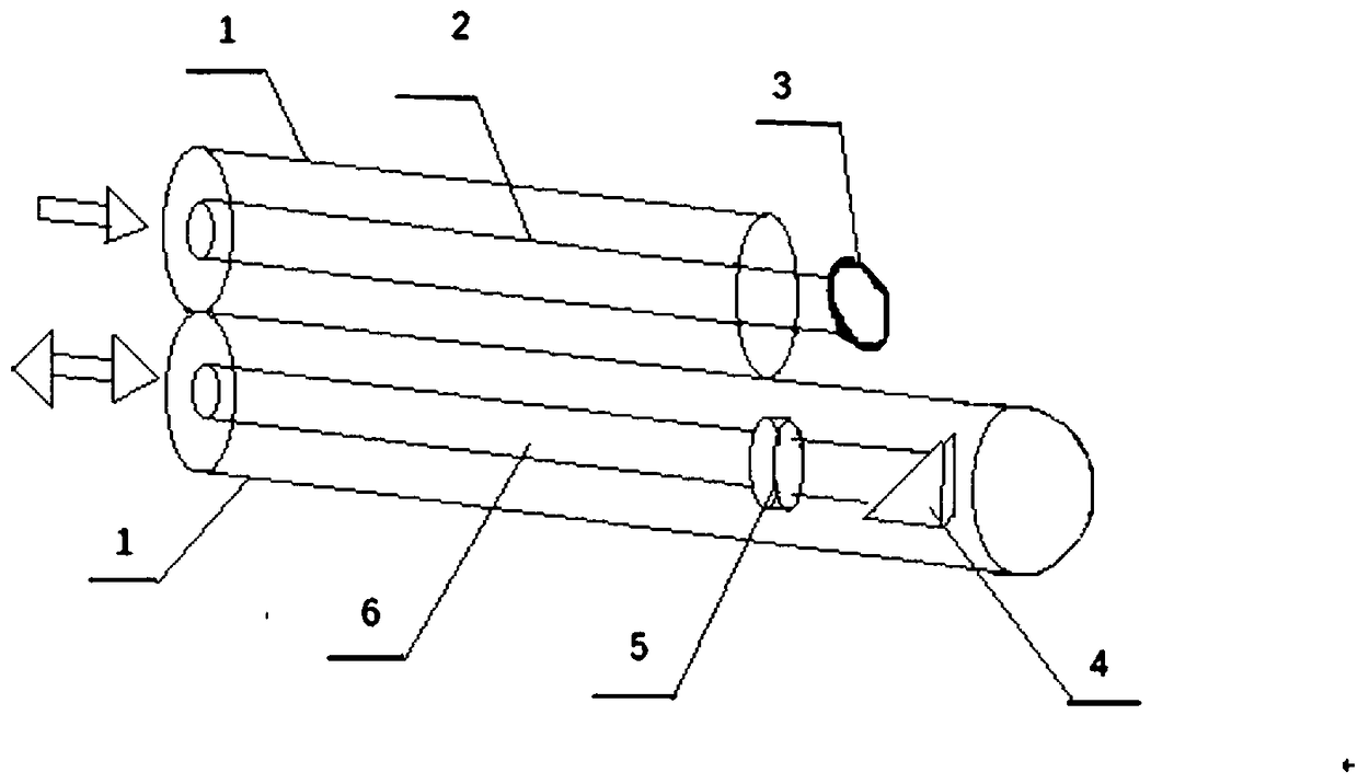
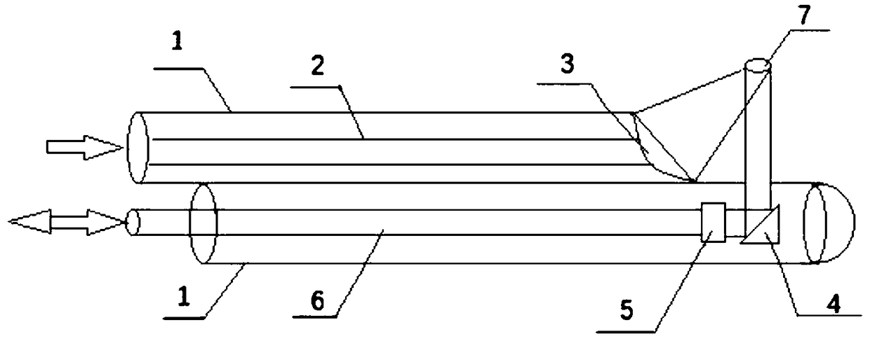
[0042] figure 1 is a schematic diagram of the three-dimensional structure of the endoscopic photoinduced ultrasound probe, figure 2 is a cross-sectional view of an endoscopic photo-ultrasound probe. First, the imaging incident fiber (6) is bonded together with the cylindrical photoinduced ultrasonic material (5). The diameter of the cylindrical photoinduced ultrasonic material (5) is 2 mm. The center of circle of material (5) is on the same straight line. Then, the therapeutic incident optical fiber (2) and the focused photo-induced ultrasonic material (3) are bonded together, the focused photo-induced ultrasonic material (3) has a diameter of 2 millimeters, and there is no gap between the two. The total reflection mirror (4) is fixed on the right side of the cylindrical photo-ultrasonic material (5), and the axis of the total reflection mirror (4) is on the same line as the center of the cylindrical photo-ultrasonic material (5). A layer of casing (1) is respectively wrap...
Embodiment 2
[0045] figure 1 is the schematic diagram of the three-dimensional structure of the photoinduced ultrasound probe, figure 2 is a cross-sectional view of the photo-ultrasonic probe. First, the imaging incident fiber (6) is bonded together with the cylindrical photoinduced ultrasonic material (5). The diameter of the cylindrical photoinduced ultrasonic material (5) is 3 mm. The center of circle of material (5) is on the same straight line. Then, the therapeutic incident optical fiber (2) and the focused photo-induced ultrasonic material (3) are bonded together. The focused photo-induced ultrasonic material (3) has a diameter of 5 mm, and there is no gap between the two. The total reflection mirror (4) is fixed on the right side of the cylindrical photo-ultrasonic material (5), and the axis of the total reflection mirror (4) is on the same line as the center of the cylindrical photo-ultrasonic material (5). A layer of casing (1) is respectively wrapped outside the two incident...
Embodiment 3
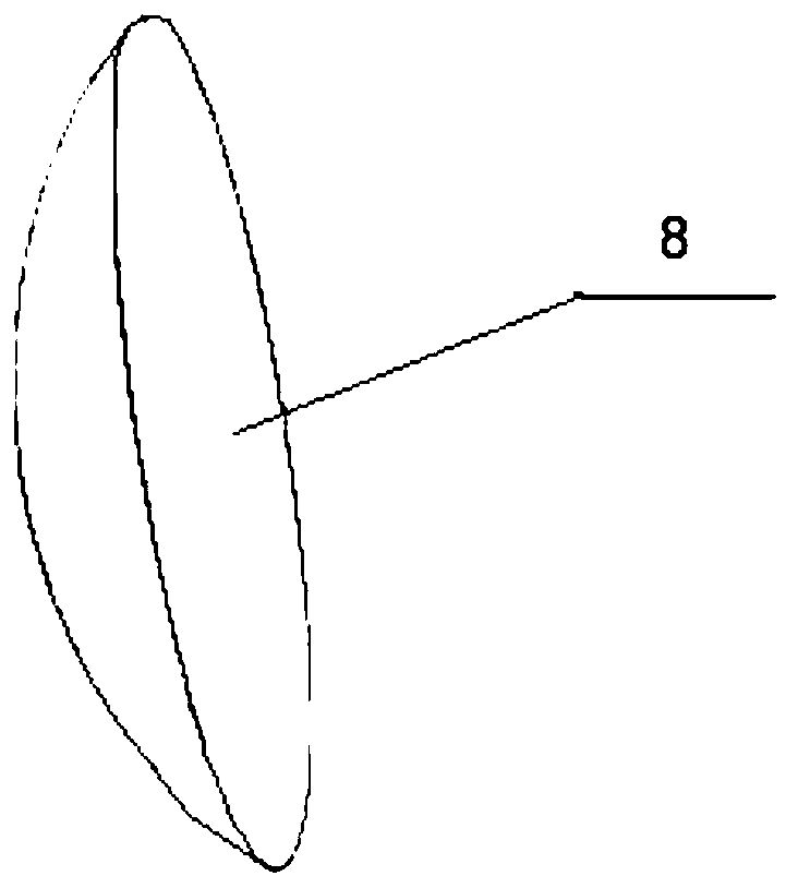
[0048] image 3 is a schematic diagram of the three-dimensional structure of the focused photo-induced ultrasound material (3), Figure 4 is a schematic diagram of the production of the focused photo-ultrasonic material (3), Figure 5 is a schematic diagram of the structure of a stereolithography apparatus based on mask image projection. The fabrication of the focused photo-ultrasonic material (3) is divided into two steps. The first step is to prepare the azeotropic mixture of methyl ethyl ketone and ethanol, and use the stainless steel grinding balls in the planetary ball mill to grind the carbon nanotube powder and the dispersant polyvinyl alcohol in the azeotropic mixture through the planetary ball mill for 10 hours. The speed is 150rpm. The mixture was then dried at 40°C for 11 hours. After evaporation of the solvent in the dispersion, a dry carbon nanotube powder can be obtained. In the second step, the carbon nanotube powder obtained in the first step is mixed with...
PUM
 Abstract
Description
Claims
Application Information
 - R&D
- Intellectual Property
- Life Sciences
- Materials
- Tech Scout
- Unparalleled Data Quality
- Higher Quality Content
- 60% Fewer Hallucinations
Browse by: Latest US Patents, China's latest patents, Technical Efficacy Thesaurus, Application Domain, Technology Topic, Popular Technical Reports.
© 2025 PatSnap. All rights reserved.Legal|Privacy policy|Modern Slavery Act Transparency Statement|Sitemap|About US| Contact US: help@patsnap.com


