Capsule endoscope and capsule endoscope system

Inactive Publication Date: 2005-03-03
OLYMPUS CORP
View PDF11 Cites 93 Cited by
  • Summary
  • Abstract
  • Description
  • Claims
  • Application Information

AI Technical Summary

Benefits of technology

[0010] It is an object of the present invention to at l

Problems solved by technology

If white balancing or the like is performed in the signal processing circuit in the capsule endoscope as done in the capsule endoscope described in Japanese Patent Application Laid-Open No. 2001-245844, however, the circui

Method used


Image

  • Capsule endoscope and capsule endoscope system
  • Capsule endoscope and capsule endoscope system
  • Capsule endoscope and capsule endoscope system

Examples


first embodiment

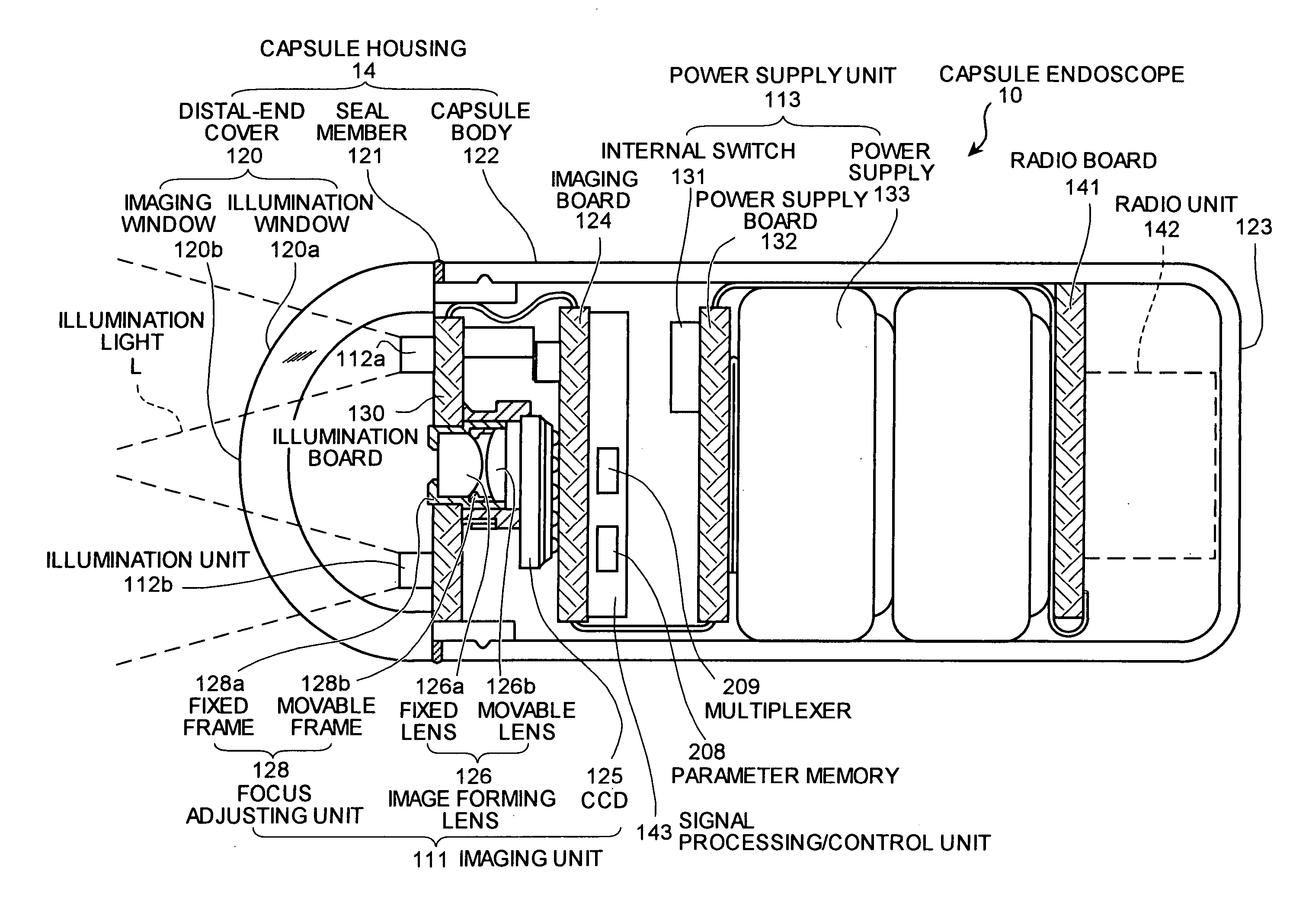
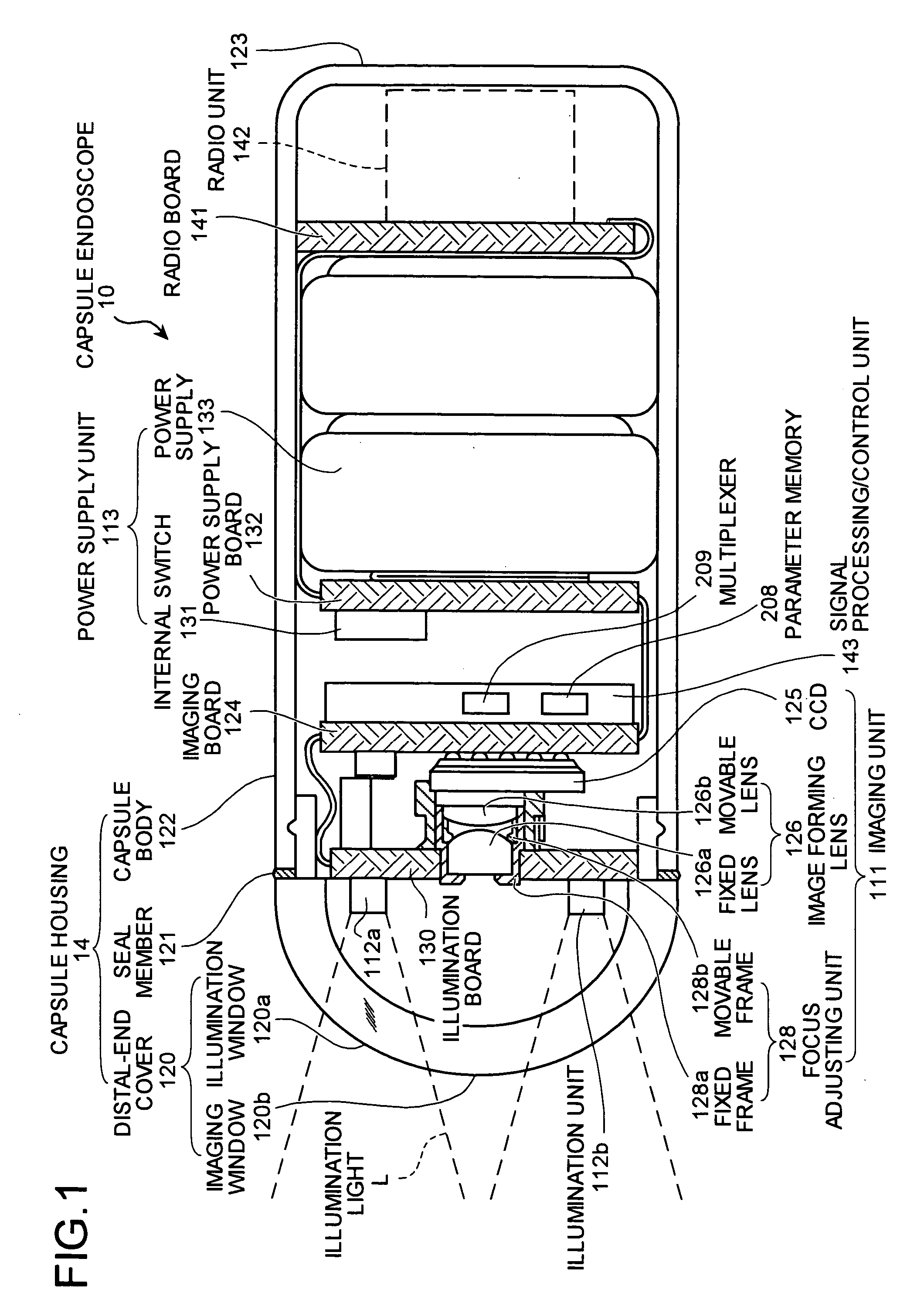
[0064] The general configuration of a capsule endoscope which is used in one embodiment of the present invention will now be explained with reference to FIG. 1. FIG. 1 is a schematic diagram of the internal configuration of the capsule endoscope according to the present embodiment. As shown in FIG. 1, a capsule endoscope 10 includes an imaging unit 111 that can take internal images of a celom, illumination units 112a and 112b that illuminate the interior of the celom, a power supply unit 113 that supplies power to those units, and a capsule housing 14 which has at least the imaging unit 111, the illumination units 112a and 112b, and the power supply unit 113 disposed inside.

[0065] The capsule housing 14 includes a distal-end cover 120 which covers the imaging unit 111 and the illumination units 112a and 112b, and a capsule body 122 which is provided in a water-proof state with respect to the distal-end cover 120 via a seal member 121 and has the imaging unit 111 and the like dispos...

second embodiment

[0160] A second embodiment will be explained with reference to FIGS. 13 and 14.

[0161] According to the second embodiment, pixel defect address data indicating the address of a defective pixel is stored in the parameter memory 208 in addition to the white balance coefficient. Correction of a pixel defect is to correct a defective pixel present at the address of the defective pixel based on the pixel data that corresponds to the addresses around the address of the defective pixel.

[0162] The other configuration of the capsule endoscope 10 is the same as that of the first embodiment. The operation of the capsule endoscope 10 and the configuration and operation of the receiver 4 are basically the same as those of the first embodiment.

[0163] In the multiplexer 209, image data, the white balance coefficient, and the pixel defect address data are multiplexed and the resultant multiplexed data is sent out from the capsule endoscope 10 via the modulator 211 and the radio unit 142. In the r...

third embodiment

[0177] A third embodiment will be explained next.

[0178] Although the first embodiment explains the example where the CCD 125 is used in the capsule endoscope 10, a CMOS image sensor is used instead of the CCD 125 in the third embodiment. The offset value of the photoelectric conversion characteristic which is specific to each CMOS image sensor is stored in the parameter memory 208 of each capsule endoscope 10 of the third embodiment. The other configuration and operation of the capsule endoscope 10 and the structure and operation of the receiver 4 are basically the same as those of the first embodiment.

[0179] In the multiplexer 209, image data and the offset value of the photoelectric conversion characteristic are multiplexed and resultant multiplexed data is sent out from the capsule endoscope 10 via the modulator 211 and the radio unit 142. In the receiver 4, the parameter detector 304 detects the parameter of the offset value of the photoelectric conversion characteristic, and ...


PUM


Abstract

A capsule endoscope includes a storage unit that stores signal processing data necessary for signal processing specific to an imaging device of a capsule endoscope, and a transmitting unit that transmits the signal processing data stored in the storage unit. Besides, a capsule endscope system includes the capsule endoscope and a receiver which receives the signal processing data transmitted from the transmittting unit. The capsule endoscope does not perform signal processing specific to the imaging device but the receiver performs signal processing specific to the imaging device based on the received signal processing data.

Description

CROSS-REFERENCE TO RELATED APPLICATIONS [0001] This application claims the benefit of priority of Japanese Patent Application No. 2003-180138 filed on Jun. 24, 2003, and the disclosure of which is incorporated herein by its entirely. BACKGROUND OF THE INVENTION [0002] 1) Field of the Invention [0003] The present invention relates to a capsule endoscope and a capsule endoscope system. [0004] 2) Description of the Related Art [0005] There is known a capsule endoscope (swallowable capsule endoscope for medical use) which is designed as to be swallowable through the mouth of a patient and which can take images of digestive systems, such as a stomach, to gather information on inside the celom of a living body. One capsule endoscope of this type proposed has a capsule which incorporates an illumination unit including an LED or the like, a solid-state imaging device including a CCD, CMOS or the like, and a power supply unit including a battery or the like for driving the illumination unit ...

Claims


Application Information

Patent Timeline
IPC IPC(8): A61B1/05A61B5/00H04L1/00H04N5/225H04N5/232
CPCA61B1/041A61B5/0031H04L1/004H04N5/2252A61B5/7232H04N5/2256H04N5/23203H04N2005/2255H04N5/2253H04N23/555H04N23/56H04N23/51H04N23/54H04N23/66A61B1/04
Inventor HONDA, TAKEMITSUKIMOTO, SEIICHIROSHIGEMORI, TOSHIAKISHIMIZU, HATSUOMORI, TAKESHI
Owner OLYMPUS CORP
Why Eureka
Try Eureka