Fault diagnosis apparatus

a technology of fault diagnosis and fault, which is applied in the direction of hydrodynamic testing, instruments, nuclear elements, etc., can solve the problems of long delay due to failure, failures in driving compornents such as motors, or failures in mechanism elements, etc., and achieve the effect of low cos

Inactive Publication Date: 2005-03-03
FUJIFILM BUSINESS INNOVATION CORP
View PDF6 Cites 49 Cited by
  • Summary
  • Abstract
  • Description
  • Claims
  • Application Information

AI Technical Summary

Benefits of technology

[0007] The present invention provides an apparatus capable of diagnosing failures of various compornents, statuses of the failures, or possibility of failure by means of a simple configuration, at low cost and by means of a simple determination method.

Problems solved by technology

Therefore, a long delay due to failure is not tolerated, and quick detection and solution of failures is sought.
However, failures in a driving compornent, such as a motor or a solenoid, or in a mechanism element which operates in conjunction with the driving compornent, such as a drive circuit for driving a motor or the like, generally arise more frequently than do failures in electronic parts [passive electronic parts such as resistors and capacitors, transistors, or ICs (Integrated Circuits)].
In particularly adverse environments, various anomalies or failures that are difficult to detect arise even when a device is used in accordance with a conventional method.
Recovery from the anomalies or failures involves consumption of much time and effort.

Method used


Image

  • Fault diagnosis apparatus
  • Fault diagnosis apparatus
  • Fault diagnosis apparatus

Examples


third embodiment

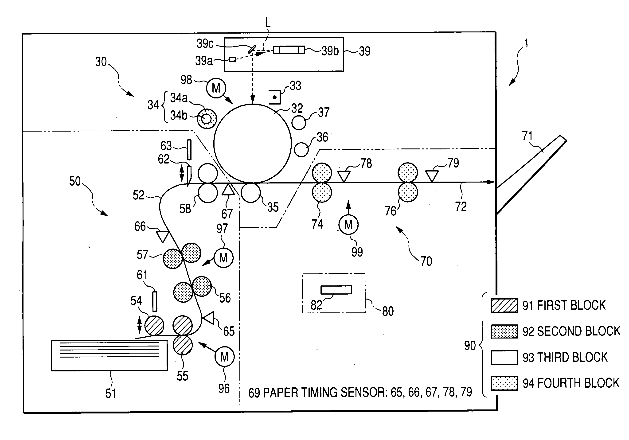
[0122]FIG. 5 is a view showing a third example of the fault diagnosis apparatus for verifying the operation state of the drive mechanism section 90. The fault diagnosis apparatus 3 of the third embodiment is characterized by using, as a signal indicating operation state of the drive mechanism section 90, a signal reflecting an operating current flowing through the driving compornents, such as a motor, a solenoid, and a clutch, and a signal reflecting vibrating state of the drive mechanism section 90 (block) to which the driving compornent belongs.

[0123] Specifically, as illustrated, the fault diagnosis apparatus 3 of the third embodiment has the drive section operating current detection section 140 of the first embodiment and the vibration detection section 180 of the second embodiment. The function and operation of the drive section operating current detection section 140 and those of the vibration detection section 180 are analogous to those of the first and second embodiments. He...

second embodiment

[0131] Since the embodiment is configured to detect an operating current and vibration on a per block basis, a determination is made, on a per block basis, as to whether or not a failure has arisen, in accordance with the operation state signal detected on a per block basis. The block determined to have failed can be subjected to more detailed fault diagnosis. The number of areas to be subjected to detailed fault diagnosis can be reduced, having previously narrowed down on a per block basis the range of object of detailed diagnosis. The configuration for determining a failure on a per block basis utilizing a paper passage time is limitedly applied to an apparatus having a mechanism for transporting a material to be transported, such as an image forming apparatus. However, utilization of the configuration of the second embodiment enables application, to every apparatus, of a mechanism which determines occurrence of a failure on a per block basis.

[0132]

[0133]FIG. 7 is a functional blo...

first embodiment

[0149] Here, in the first embodiment, measurement of the feature value Vn based on the operation state signal (either the digitized detection data Dcurr or the digitized detection data Dosci) of the drive mechanism section 90 is performed “m” times (e.g., about 100 times) (S102), thereby determining a reference value used for subsequent fault determination. For instance, a mean value Vm of the feature values Vn acquired through measurement operations and a standard deviation av are determined, and the thus-determined mean value Vm and the standard deviation av are taken as reference feature values used for detecting a fault (S104). The reference feature value storage section 230 receives the reference feature values (Vm, σv) from the operation state feature value acquisition section 210 and stores the thus-received reference feature values in the storage medium 232 (e.g., nonvolatile memory) (S106).

[0150] In connection with the other driving compornents, the fault diagnosis section ...


PUM


Abstract

A fault diagnosis section activates a driving compornent alone, measures an operation state signal and a paper passage time, and stores feature values (Vm, σv, Tqs, σts) extracted as a determination reference in a storage medium. A paper passage fault determination section determines whether or not a fault has arisen on the basis of the paper passage time when an apparatus is under normal operating conditions. A diagnosis target block determination section determines an order to operate a detail fault diagnosis when it is determined that there is a plurality of diagnosis target blocks. When the driving compornent is activated alone under actual operation conditions, the operation state signal Vf is obtained, and an operation state fault determination section conducts diagnosis on whether or not a fault has arisen on the driving compornent and a state of the fault, and whether or not a fault has arisen on other power transmission compornents and a nature of the fault with reference to the feature values as the determination reference on the basis of a degree of deviation from a normal range.

Description

BACKGROUND OF THE INVENTION [0001] 1. Field of the Invention [0002] The present invention relates to a fault diagnosis apparatus which diagnoses failures or faulty operations of a drive mechanism section used in office equipment, such as a copier, a printer, a facsimile, or a multifunction device having the features of these devices in combination, or in other equipment (e.g., an electrical household appliance, an automobile, or the like). [0003] 2. Description of the Related Art [0004] In recent years, high productivity is required of various types of machines, particularly office equipment such as copiers or printers. Therefore, a long delay due to failure is not tolerated, and quick detection and solution of failures is sought. [0005] Other industrial equipment, such as automobiles, aircraft, robots, and semiconductor design systems, are equipped, as means for operation control, with a plurality of highly reliable compornents which can operate at high speed with high accuracy. Ho...

Claims


Application Information

Patent Timeline
Patent Type & Authority Applications(United States)
IPC IPC(8): B41J29/38B65H7/06B41J29/46G01R31/28G03G21/00G06F11/00H04N1/00
CPCB41J29/38
Inventor YASUKAWA, KAORUADACHI, KOJINAKAGAWA, EIGOSATONAGA, TETSUICHIYAMADA, NORIKAZUUWATOKO, KOKI
Owner FUJIFILM BUSINESS INNOVATION CORP
Why Eureka
Try Eureka