The use of a layout-optimization tool to increase the yield and reliability of VLSI designs

a layout optimization and design technology, applied in the direction of cad circuit design, program control, instruments, etc., can solve the problem that the attempt to do such layout modification by hand would be prohibitively expensiv

Inactive Publication Date: 2005-03-03
INTELLECTUAL DISCOVERY INC
View PDF5 Cites 11 Cited by
  • Summary
  • Abstract
  • Description
  • Claims
  • Application Information

AI Technical Summary

Benefits of technology

[0005] The invention provides a method for optimizing placement of redundant vias within an integrated circuit design. The invention first locates target vias by determining which vias do not have a redundant via. Then, the invention draws marker shapes on, or adjacent to, the target vias. The marker shapes are only drawn in a horizontal or vertical direction from each of the target vias. Next, the invention uses an optimizer to simultaneously expand all of the marker shapes in the first direction to a predetermined length or until the marker shapes reach the limits of a ground rule. During the expanding, different marker shapes will be expanded to different lengths. The invention determines which of the marker shapes were expanded sufficiently to form a valid redundant via to produce a first set of potential redundant vias and the invention eliminates marker shapes that could not be expanded sufficiently to form a valid redundant via. The invention repeats the foregoing processing in the direction perpendicular to the first, again using an optimizer to determine which marker shapes from this second pass of potential redundant vias produce the highest number of redundant vias. The invention then adds the redundant vias to the integrated circuit design, according to output produced by the optimizer.

Problems solved by technology

The advantages of automating the insertion of redundant contacts or the separating of vias are self-evident; VLSI designs can contain millions of vias, and any attempt to do such layout modification by hand would be prohibitively expensive.

Method used


Image

  • The use of a layout-optimization tool to increase the yield and reliability of VLSI designs
  • The use of a layout-optimization tool to increase the yield and reliability of VLSI designs
  • The use of a layout-optimization tool to increase the yield and reliability of VLSI designs

Examples


Embodiment Construction

[0022] The present invention and the various features and advantageous details thereof are explained more fully with reference to the nonlimiting embodiments that are illustrated in the accompanying drawings and detailed in the following description. It should be noted that the features illustrated in the drawings are not necessarily drawn to scale. Descriptions of well-known components and processing techniques are omitted so as to not unnecessarily obscure the present invention in detail.

[0023] Specific embodiments of the invention will now be further described by the following, nonlimiting examples which will serve to illustrate in some detail various features of significance. The examples are intended merely to facilitate an understanding of ways in which the invention may be practiced and to further enable those of skill in the art to practice the invention. Accordingly, the examples should not be construed as limiting the scope of the invention.

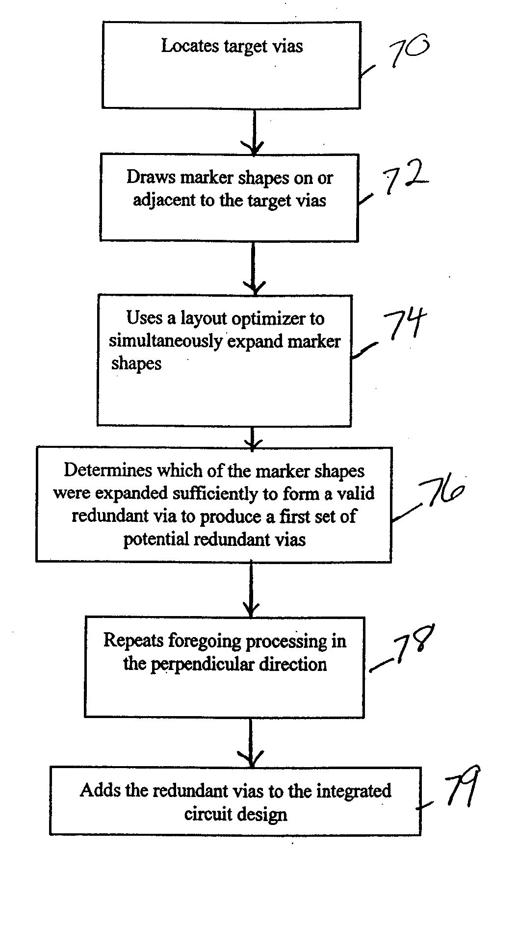
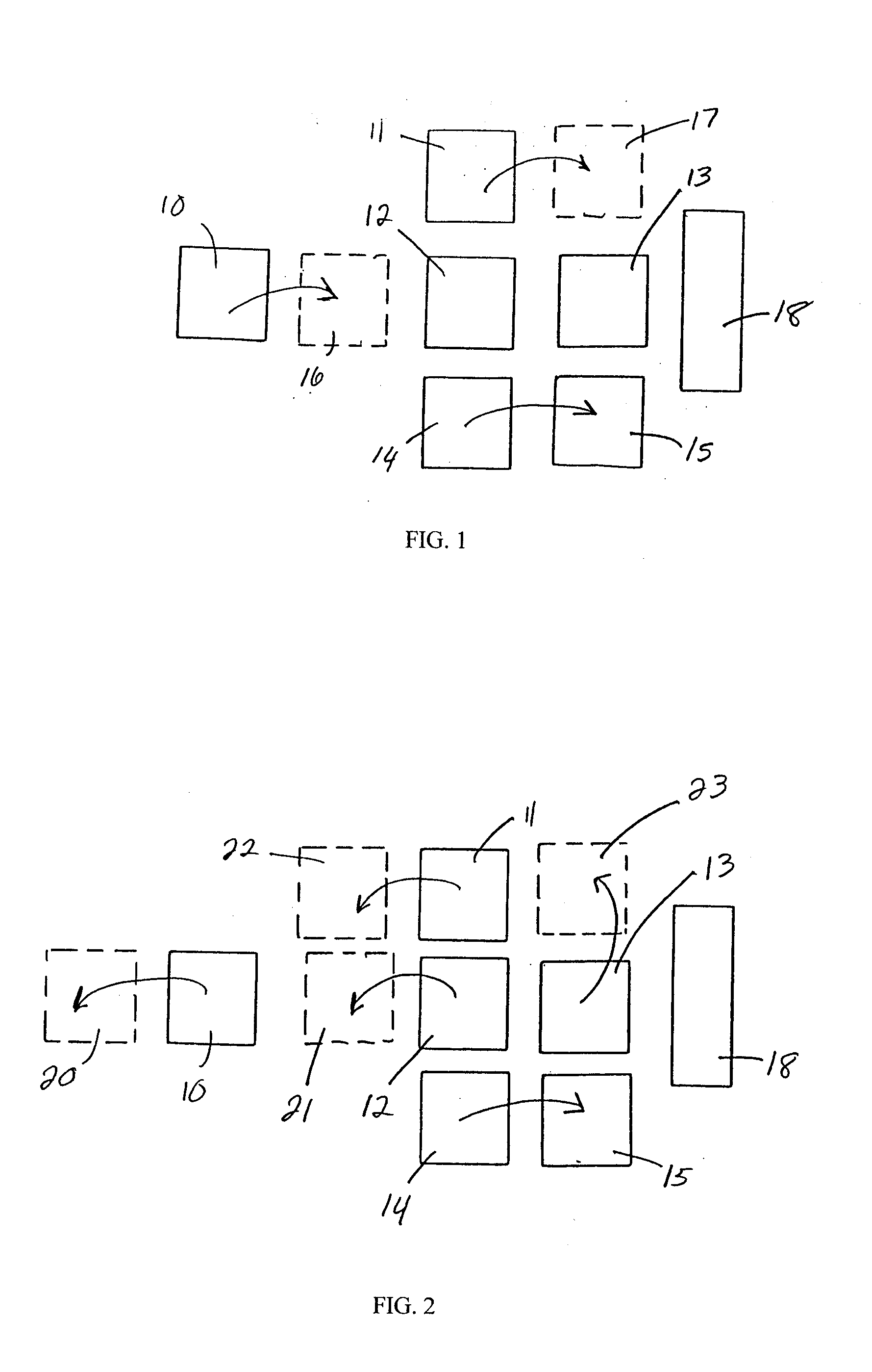
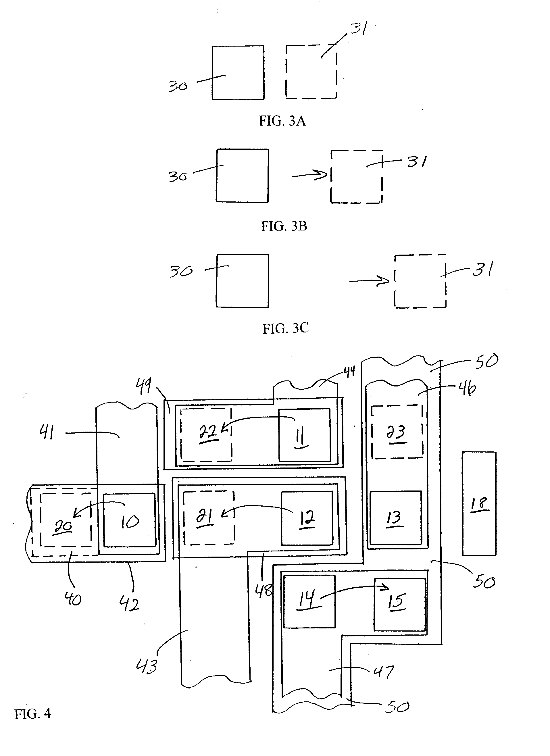
[0024] The invention optimizes...


PUM


Abstract

The invention provides a method and structure for optimizing placement of redundant vias within an integrated circuit design. The invention first locates target vias by determining which vias do not have a redundant via. Then, the invention draws marker shapes on or adjacent to the target vias. The marker shapes are only drawn in a horizontal or vertical direction from each of the target vias. Next, the invention simultaneously expands all of the marker shapes in the first direction to a predetermined length or until the marker shapes reach the limits of a ground rule. During the expanding, different marker shapes will be expanded to different lengths. The invention determines which of the marker shapes were expanded sufficiently to form a valid redundant via to produce a first set of potential redundant vias and the invention eliminates marker shapes that could not be expanded sufficiently to form a valid redundant via. The invention repeats the foregoing processing in the direction perpendicular to the first. The invention can also be used to eliminate certain undesirable structures such as stacked vias or can be used to fix other problems such as insufficient via-to-via spacing. The invention then adds the redundant vias to the integrated circuit design, according to output produced by the optimizer.

Description

BACKGROUND OF INVENTION [0001] 1. Field of the Invention [0002] The present invention generally relates to increasing the yield of integrated circuit devices and more particularly to an improved methodology for forming redundant vias and increasing spacing between vias. [0003] 2. Description of the Related Art [0004] Due to the nature of the CMOS manufacturing process, it is sometimes desirable to modify a ground-rule-correct VLSI design for the purpose of increasing reliability or manufacturing yield. One way to achieve this is to add redundancy to contacts or vias, and in certain circumstances, it is beneficial to increase the spacing between vias that are on the same level or are on different levels. The advantages of automating the insertion of redundant contacts or the separating of vias are self-evident; VLSI designs can contain millions of vias, and any attempt to do such layout modification by hand would be prohibitively expensive. In addition, by automating these activities...

Claims


Application Information

Patent Timeline
Patent Type & Authority Applications(United States)
IPC IPC(8): G06F9/45G06F17/50
CPCG06F17/5068G06F30/39
Inventor ALLEN, ROBERT J.HIBBELER, JASON D.TELLEZ, GUSTAVO E.
Owner INTELLECTUAL DISCOVERY INC
Why Eureka
Try Eureka