
Circular tubular heat pipe having a sealed structure closing a distal opening thereof

a tubular heat pipe and sealed technology, applied in the direction of indirect heat exchangers, light and heating apparatus, etc., can solve the problems of cpu even stopping working, wasting time, increasing cost, etc., to facilitate pretreatment of heat pipes, shorten welding time, and reduce cost

Inactive Publication Date: 2005-03-10
HSU HUL CHUN
View PDF2 Cites 15 Cited by
  • Summary
  • Abstract
  • Description
  • Claims
  • Application Information

AI Technical Summary

Benefits of technology

[0012] It is the main object of the present invention to provide a circular tubular heat pipe having a sealed structure closing a distal opening thereof, which reduces an area of a sealed welding portion of the heat pipe, shortens the welding time and, in particular, can be applied to a heat pipe with a large diameter of the distal opening.
[0013] It is another object of the present invention to provide a circular tubular heat pipe having a sealed structure closing a distal opening thereof, which eliminates the shrinking process of the distal opening of the heat pipe so as to reduce the cost.
[0014] It is still another object of the present invention to provide a circular tubular heat pipe having a sealed structure closing a distal opening thereof, which facilitates the pretreatment of the heat pipe, such as simplifying and accelerating the insertion of the capillary material and the charge of working fluid so as to improve the stability of the functions and quality of the heat pipe.
[0015] According to the present invention, the circular tubular heat pipe has a sealed structure closing a distal opening thereof. The improvement of the sealed structure comprises a concave wall portion formed on the heat pipe adjacent to the distal opening. A pressed recess portion is formed on the concave wall portion adjacent to the distal opening, the heat pipe being formed to have a overlapping wall at the pressed recess portion. A volume reduced portion is formed on the pressed recess portion adjacent to the distal opening, and a sealed welding portion formed on the volume reduced portion at the distal opening, thereby reducing an area of the sealed welding portion. As the formation of the pressed recess portion and the volume reduced portion reduces the area of the sealed welding portion, the shrinking process is eliminated, and the welding time of the heat pipe with a large diameter is shortened.

Problems solved by technology

As a result, the operating velocity slows down or the CPU may even stops working.
However, the capillary material exposing out of the distal opening is unstable after the shrinking process, and the charge of working fluid has to be done by a manual process, which wastes time and increases cost.
Inserting the capillary material and injecting the working fluid after the heat pipe is shrinked is also difficult and will increase the manufacturing steps and cost.
Furthermore, when sealing a heat pipe with large dimensions, a large area and long welding path have to be welded.
A special welding machine is required, which is expensive, as well as a very serious welding technology.
Otherwise, it will take a very long time to complete the welding process.
Because the heat pipe has a high heat conductive property, the welding circuit is large, and the welding time is long, heat will be conducted to the welding machine and molds and damage them.

Method used


Image

  • Circular tubular heat pipe having a sealed structure closing a distal opening thereof
  • Circular tubular heat pipe having a sealed structure closing a distal opening thereof
  • Circular tubular heat pipe having a sealed structure closing a distal opening thereof

Examples


Embodiment Construction

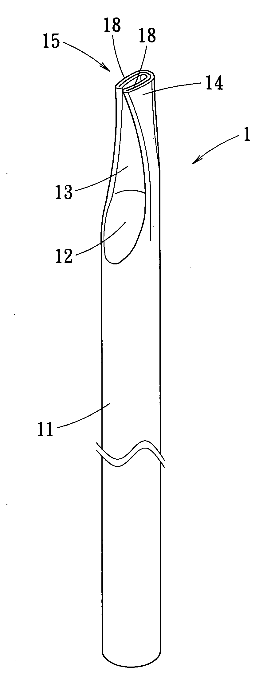
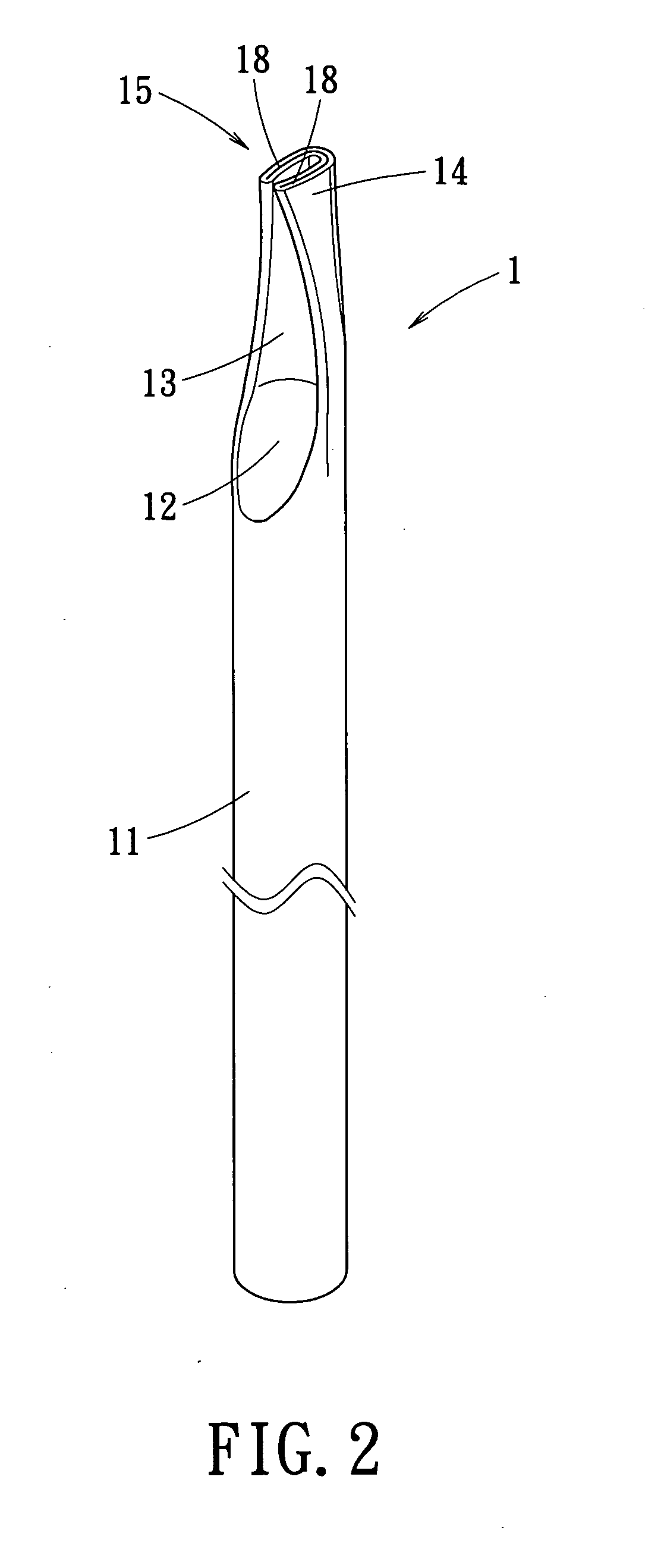
[0032] Referring to FIG. 2, a circular tubular heat pipe having a sealed structure closing a distal opening 15 thereof in accordance with the present invention is shown. A method for fabricating the sealed structure comprises:

[0033] Step 1: pressing a region of the heat pipe adjacent to the distal opening 15 to pinch a circular tubular pipe formed an overlapping wall thereof.

[0034] Referring to FIG. 3 and FIG. 4, placing the distal opening 15 of the heat pipe to a press mold set including an upper mold 16 and a lower mold 17. A region of the heat pipe adjacent to the distal opening 15 is pressed to form a concave wall portion 12 as shown in FIG. 5. A pressed recess portion 13 is formed on the concave wall portion 12 adjacent to the distal opening 15. The heat pipe is formed to have a overlapping wall at the pressed recess portion 13. A pair of wing portions 18 is formed on the pressed recess portion 13 adjacent to the distal opening 15. The pressed recess portion 13 can be further...


PUM

PropertyMeasurementUnit
Diameteraaaaaaaaaa
Volumeaaaaaaaaaa
Shapeaaaaaaaaaa

Abstract

A circular tubular heat pipe has a sealed structure closing a distal opening thereof. The improvement of the sealed structure provides a concave wall portion formed on the heat pipe adjacent to the distal opening. A pressed recess portion is formed on the concave wall portion adjacent to the distal opening, the heat pipe being formed to have a overlapping wall at the pressed recess portion. A volume reduced portion is formed on the pressed recess portion adjacent to the distal opening. A sealed welding portion is formed on the volume reduced portion at the distal opening, thereby reducing an area of the sealed welding portion. As the formation of the pressed recess portion and the volume reduced portion reduces the area of the sealed welding portion, the shrinking process is eliminated, and the welding time of the heat pipe with a large diameter is shortened.

Description

BACKGROUND OF THE INVENTION [0001] 1. Field of the Invention [0002] The present invention relates to a circular tubular heat pipe having a sealed structure closing a distal opening thereof and, more particularly, to a heat pipe having a sealed structure without using a shrinking process for reducing a diameter of the distal opening. [0003] 2. Description of the Related Art [0004] Whether the performance of an electronic product is good enough depends on its operating velocity, and the problem of heat dissipation of an electronic element in the electronic product is the major influence on operating velocity. [0005] For example, a CPU (central processing unit) on a mother board of a computer is in charge of command and signal transmission as well as program and numerical calculation, which provide a very fast frequency to the CPU and produce high temperatures that further influence the electronic property of the CPU. As a result, the operating velocity slows down or the CPU may even s...

Claims


Application Information

Patent Timeline
IPC IPC(8): F28D15/02
CPCY10T29/49353F28D15/0283
Inventor HSU, HUL CHUN
Owner HSU HUL CHUN
Learn More