Display device

Active Publication Date: 2005-03-10
SANYO ELECTRIC CO LTD +1
View PDF5 Cites 29 Cited by
  • Summary
  • Abstract
  • Description
  • Claims
  • Application Information

AI Technical Summary

Benefits of technology

[0005] An object of the present invention is to provide a self-illuminating display devic

Problems solved by technology

However, since LCDs are not self-illuminating, they suffer from narrow viewing angles, and require a light source such as a backlight, which makes it impossible to reduce power consumption beyond a certain limit.
Inconveniently, however, with the drive and control TFTs formed as polysilicon TFTs, the display device needs to be fabricated through a complicated, difficult fabrication pro

Method used


Image

  • Display device
  • Display device
  • Display device

Examples


Example

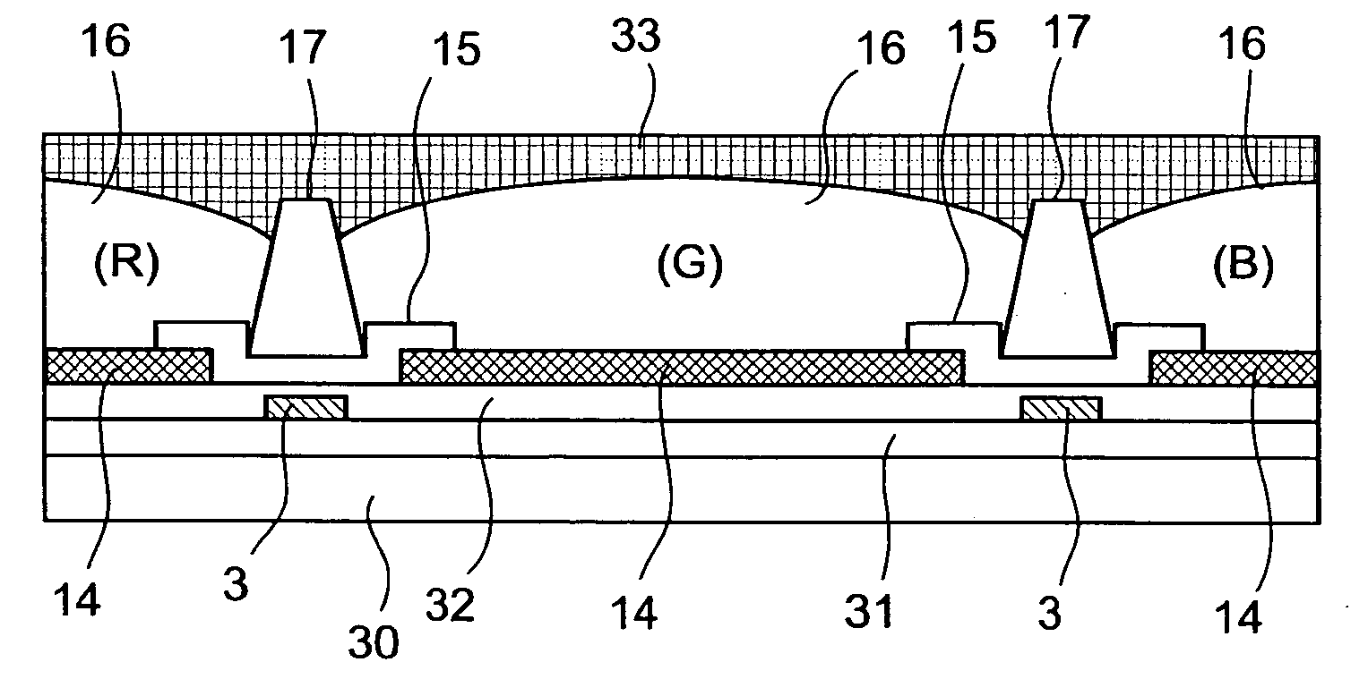
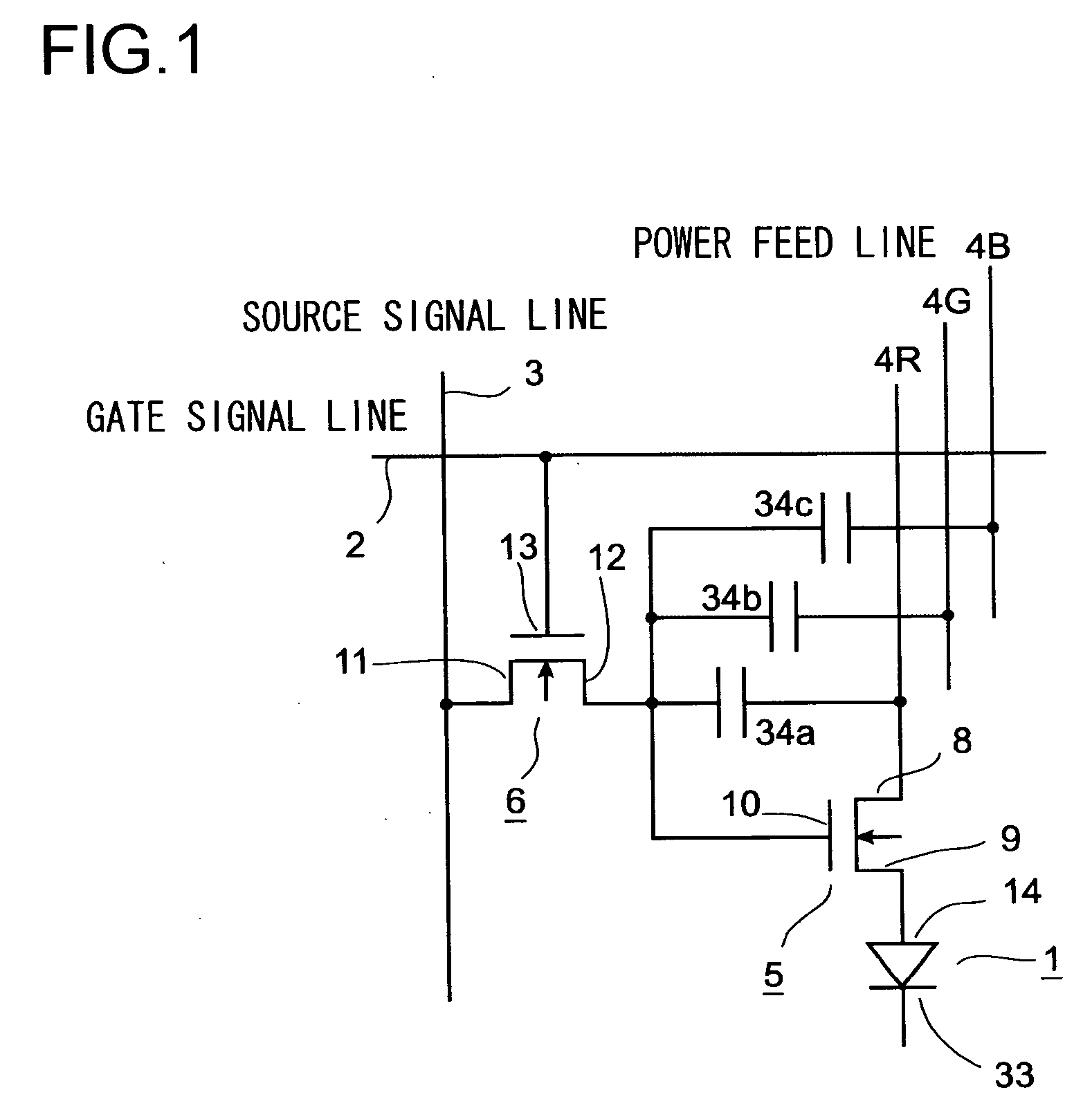
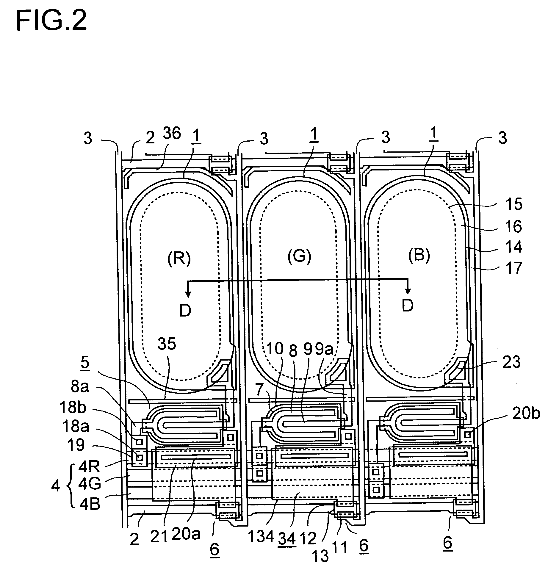
[0031] Hereinafter, an embodiment of the present invention will be described with reference to the drawings. FIG. 1 is a diagram schematically showing the circuit configuration of a pixel in a display device according to the invention. FIG. 2 is a plan view showing pixels of the display device and a portion around it. FIG. 3 is a schematic cross-sectional view (taken along line D-D shown in FIG. 2) of the light-emitting element formed within the pixel. In this embodiment, the light-emitting element is realized with an organic EL element 1. It should be noted that, while a common electrode 33 is shown in FIG. 3, it is omitted in FIG. 2 to make the figure easy to view.

[0032] As shown in FIG. 1, the organic EL element 1 emits light when a current flows therethrough from a pixel electrode 14 to a common electrode 33, and its brightness can be adjusted by controlling the level of the current. The organic EL element 1 of a particular pixel is made to emit light in the following manner. A...


PUM


Abstract

A display device includes a plurality of light emitting elements arranged in a matrix. A scan signal is made to flow into a gate signal line and a data signal is made to flow into a source signal line so that the data signal is applied to a source electrode and the scan signal is supplied to a gate electrode of a control TFT arranged at a portion where the both signal lines intersect when viewed from above. Thus, when the control TFT is turned ON, a drive TFT having a gate electrode connected to the drain electrode is turned ON, so that current is supplied from a power supply line via the source electrode and the drain electrode of the drive TFT to an organic EL element and the organic EL element emits light. A holding capacity is present between the control TFT and the drive TFT. Even when the scan signal becomes LOW level and the control TFT turns OFF, the gate potential of the drive TFT is held for a predetermined period of time by the holding capacity and the organic EL element continues to emit light.

Description

TECHNICAL FIELD [0001] The present invention relates to a display device having light-emitting elements arrayed in a matrix-like pattern. BACKGROUND ART [0002] Nowadays, LCDs are widely used as flat panel displays in various appliances ranging from cellular phones to large-screen television monitors. However, since LCDs are not self-illuminating, they suffer from narrow viewing angles, and require a light source such as a backlight, which makes it impossible to reduce power consumption beyond a certain limit. To avoid these inconveniences, as alternatives to LCDs, self-illuminating display devices exploiting, for example, organic electroluminescence (hereinafter referred to as organic EL) are being studied. [0003] This type of display device has, as pixels, organic EL elements arranged in a matrix-like pattern, and achieves image display by driving those organic EL elements to emit light individually. In a case where they are driven by an active matrix method, a thin-film transistor...

Claims


Application Information

Patent Timeline
IPC IPC(8): G02F1/1362G02F1/1368G09G3/32H01L27/32
CPCG02F1/136213H01L29/78633G02F1/1368G09G3/3233G09G2300/0417G09G2300/0426G09G2300/0852G09G2310/0235G09G2320/0214G09G2320/0242H01L27/1214H01L27/3211H01L27/3244H01L27/3246H01L27/3262H01L27/3272H01L29/41733H01L29/42384G02F1/13624H01L27/124H10K59/35H10K59/122H10K59/126H10K59/1213H05B33/00G09F9/30H05B33/14H10K59/12
Inventor MORITA, SATOSHITANAKA, SHINICHIROKOBAYASHI, OSAMU
Owner SANYO ELECTRIC CO LTD
Why Eureka
Try Eureka