
Location patterns and methods and apparatus for generating such patterns

a technology of location patterns and patterns, applied in the field of location patterns, can solve the problems of many existing home and office printers, for example, being unable to reliably print the elements of such patterns, and achieve the effect of improving the reliability of the effect of printing

Inactive Publication Date: 2005-03-10
HEWLETT PACKARD DEV CO LP
View PDF43 Cites 26 Cited by
  • Summary
  • Abstract
  • Description
  • Claims
  • Application Information

AI Technical Summary

Benefits of technology

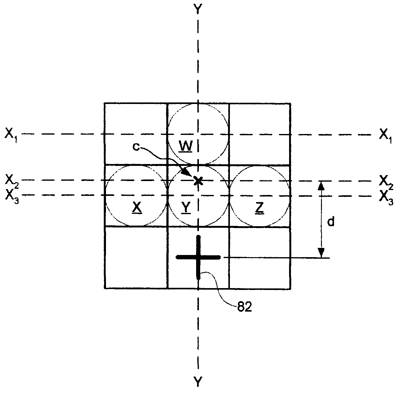
The invention is a printer system that can print a pattern of dots with a specific size and position. The system can modify some of the dots before printing to make them have a more accurate optical center of gravity. This improves the accuracy of the printed pattern. The invention also includes software and a printer driver to generate this pattern and methods for printing it.

Problems solved by technology

One problem avoided by such a system is that of users who design their own forms or documents, printing human-discernable or readable content over the dot pattern with the wrong ink (ink that is IR-absorbing ink), thereby masking the dot pattern from the digital pen, when the pen is used.
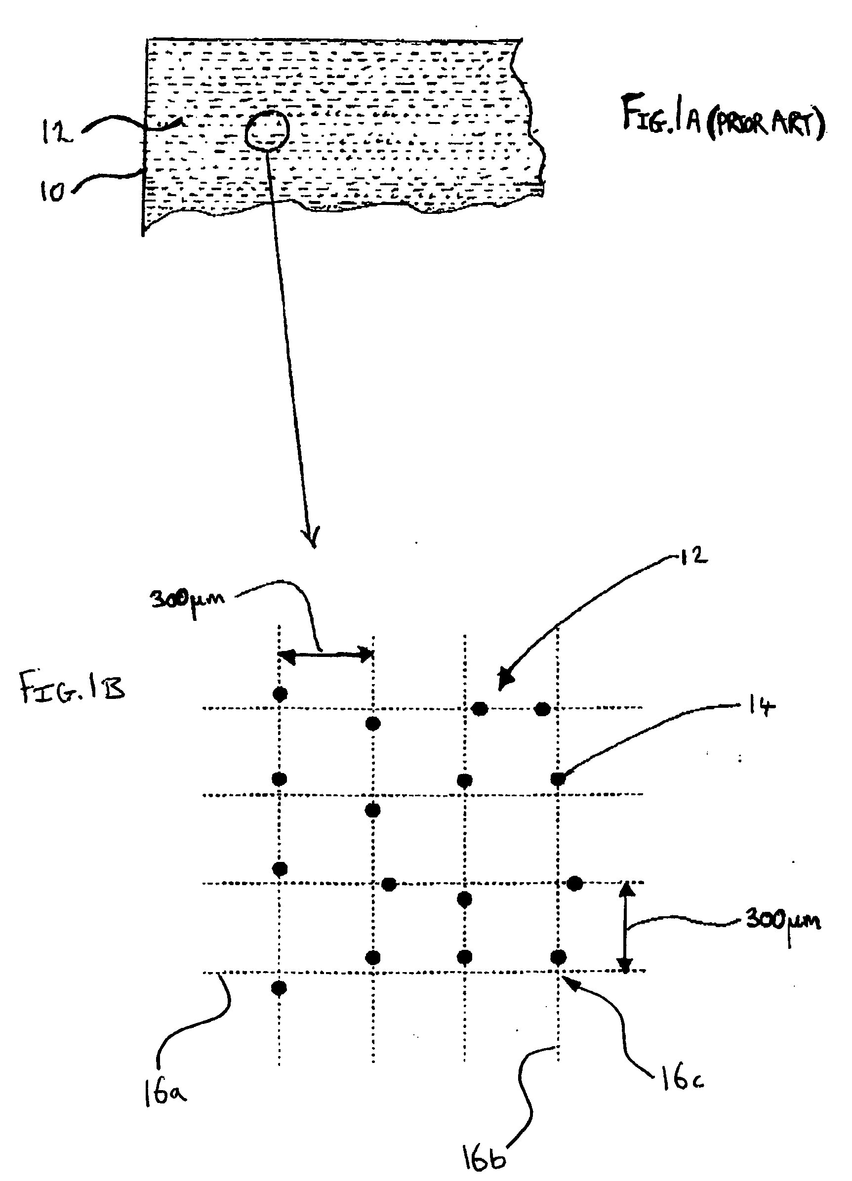
Many printers have technical characteristics which render them unable to reliably print the elements of such a pattern, such that the relative positions and the sizes of the pattern elements meet the pre-set tolerances.
Many existing home and office printers, for example, are unable to reliably do so.

Method used


Image

  • Location patterns and methods and apparatus for generating such patterns
  • Location patterns and methods and apparatus for generating such patterns
  • Location patterns and methods and apparatus for generating such patterns

Examples


Embodiment Construction

[0025] There will now be described, by way of example only, the best mode contemplated by the inventors for carrying out embodiments of the invention.

[0026]FIG. 3 is a schematic illustration of a system 50 for printing a document having a pattern, according to an embodiment of the invention.

[0027] The system 50 comprises a workstation 51 including a personal computer (PC) 52 which is connected to a local printer 60. In practice, the printer may instead be connected to the PC 52 via a network. The PC 52 may also be connected to the Internet 62. The PC 52 includes a user interface including a screen 58, a keyboard 54 and a mouse 56. The PC 52 has as a processor 52a, a memory 52b, and I / O software devices 52c by means of which the processor communicates with the screen 58, the keyboard 54 and the mouse 56 and a communications port 57 by means of which it communicates with the Internet 62 or a local network such as a LAN 59 having peripheral devices and / or other computers (e.g. PCs) 5...


PUM


Abstract

A printer system comprising a printer adapted to print a location pattern comprising a plurality of dots, each having a substantially predetermined size and nominal position in the pattern, the printer having a resolution constraining the position at which the dots may be printed, the system being adapted to modify at least some of the dots prior to printing such that the modified dots have an optical centre of gravity that more closely coincides with their nominal positions.

Description

CROSS REFERENCE TO RELATED APPLICATIONS [0001] This application is related to the following Patent Applications: U.S. patent application Ser. No.______ filed Sep. 10, 2003, entitled “Printing Digital Documents” (HP reference 200207150-1; Attorney docket 621239-6); U.S. patent application Ser. No. ______ filed Sep. 10, 2003, entitled “Methods and Apparatus for Generating Images” (HP reference 200207059-1; Attorney docket 621240-1); U.S. patent application Ser. No.______ filed Sep. 10, 2003, entitled “Location Patterns And Methods And Apparatus For Generating Such Patterns” (HP reference 200310543-1; Attorney docket 621242-7); British Patent Application No.______ filed Sep. 10, 2003, entitled “Methods, apparatus and software for printing location pattern” (HP reference 200300566-1; Attorney docket JL3824), the disclosure of which is hereby incorporated herein by reference; and, British Patent Application No.______ filed Sep. 10, 2003, entitled “Printing of documents with position iden...

Claims


Application Information

Patent Timeline
Patent Type & Authority Applications(United States)
IPC IPC(8): G06K15/02
CPCG06K1/121G06K2215/0082G06K15/02
Inventor NELSON, TERRY M.
Owner HEWLETT PACKARD DEV CO LP
Learn More