Illuminator

a technology of illumination and light source, which is applied in the field of illumination, can solve the problems of unmatched light source and image forming device, increased manufacturing costs, and increased manufacturing costs, and achieves the effects of reducing manufacturing costs, simple assembly process, and minimizing the effect of light sour

Inactive Publication Date: 2005-03-10
SAMSUNG ELECTRONICS CO LTD
View PDF13 Cites 29 Cited by
  • Summary
  • Abstract
  • Description
  • Claims
  • Application Information

AI Technical Summary

Benefits of technology

[0023] The present general inventive concept provides an illuminator that has low manufacturing costs, a simple assembly process, minimizes effects on a light source, and can dynamically control etendue by varying the size of an aperture.

Problems solved by technology

Otherwise, the etendue of the light source and that of the image forming device will be unmatched and light loss will occur.
In an illuminator having the above-described structure, the additional retro-reflector 15 increases manufacturing costs and furthermore complicates the manufacturing process required for a proper alignment of the retro-reflector.
Moreover, it is difficult to dynamically control the etendue because the size of an aperture is fixed.
Also, about half of the total light emitted from a light source will be projected back to the light source, thus reducing the life span of the light source.
However, in such an illuminator, it is difficult to dynamically control etendue because the size of the retro-reflector is fixed.
Also, about half of the total light emitted from the light source will be reflected back to the light source, thus reducing the life span of the light source.
However, in such an illuminator, it is difficult to dynamically control the etendue because the size of the retro-reflector is fixed.
Also, about half of the total light emitted from the light source will be reflected back to the light source, thus reducing the life span of the light source.

Method used


Image

  • Illuminator
  • Illuminator
  • Illuminator

Examples


Embodiment Construction

[0038] Reference will now be made in detail to the embodiments of the present general inventive concept, examples of which are illustrated in the accompanying drawings, wherein like reference numerals refer to the like elements throughout. The embodiments are described below in order to explain the present general inventive concept by referring to the figures.

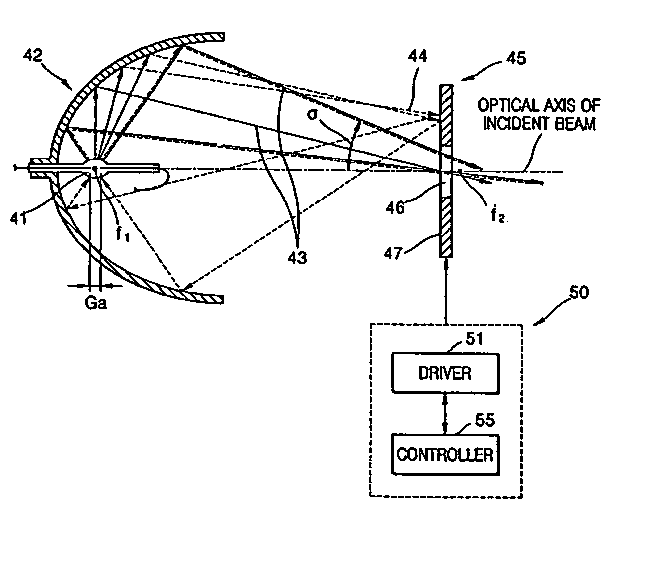
[0039] Referring to FIG. 4, an illuminator according to an embodiment of the present general inventive concept includes a light source 41 generating and emitting light, a concave reflector 42 directing the emitted light in a predetermined direction, and a retro-reflector 45 placed face-to-face with the concave reflector 42. The light source 41 is interposed between the retro-reflector 45 and the concave reflector 42. The retro-reflector 45 lies in a path of a beam reflected from the concave reflector 42, has an aperture 46 transmitting part of the beam and a specular surface 47 reflecting back a remaining part of the beam. The...


PUM


Abstract

An illuminator in which etendue of collected light emitted from a light source can be dynamically controlled. The illuminator includes a light source generating and emitting light, a concave reflector reflecting the light in a predetermined direction, and a retro-reflector placed in the path of the light reflected by the concave reflector. The retro-reflector has an aperture transmitting some of the light and a specular surface reflecting the rest of the light toward the concave reflector.

Description

CROSS-REFERENCE TO RELATED APPLICATIONS [0001] This application claims the priority of Provisional Patent Application No. 60 / 500,688, filed on Sep. 8, 2003, in the United States Patent and Trademark Office, and the priority of Korean Patent Application No. 2003-82337, filed on Nov. 19, 2003, in the Korean Intellectual Property Office, the disclosure of which is incorporated herein in its entirety by reference.BACKGROUND OF THE INVENTION [0002] 1. Field of the Invention [0003] The present general inventive concept relates to an illuminator emitting light generated by a light source in one direction, and more particularly, to an illuminator in which an etendue of light emitted from a light source can be dynamically controlled. [0004] 2. Description of the Related Art [0005] Typically, an illuminator is widely used as a light source of an image projection apparatus forming an image by using an image forming device, such as a liquid crystal display device or a digital micro-mirror devic...

Claims


Application Information

Patent Timeline
Patent Type & Authority Applications(United States)
IPC IPC(8): G02B27/00F21V8/00G02B5/00G02B17/06G02B27/09H04N5/74
CPCG02B5/005G02B6/0001G02B27/0994G02B19/0028H04N9/3141G02B19/0023G02B19/0047H04N5/7416G02B27/00
Inventor SOKOLOV, KIRILL
Owner SAMSUNG ELECTRONICS CO LTD
Why Eureka
Try Eureka