System of several stacker cranes, and a method for controlling the same

a technology of stacker crane and system, which is applied in the direction of lifting devices, loading/unloading, storage devices, etc., can solve the problems of insufficient length distribution of pieces, inability to always know the length distribution of pieces in advance, and insufficient rack space, so as to increase the capacity of the rack system, the effect of increasing the capacity

Inactive Publication Date: 2005-03-10
FASTEMS
View PDF8 Cites 53 Cited by
  • Summary
  • Abstract
  • Description
  • Claims
  • Application Information

AI Technical Summary

Benefits of technology

[0010] It is an aim of the present invention to eliminate the above-presented problems and to make it possible to increase the capacity of the rack system and to use the stacker cranes in a significantly more efficient way. Above all, the system is designed so that the most suitable stacker crane equipment is always in use, wherein e.g. during the manipulation of cases or goods of short dimensions, the capacity can be increased from that of prior art, and the size or weight of the equipment will not be an obstacle. Thanks to the lighter equipment, more storage space is obtained in the ends of the racks, and moreover, the upper and lower spaces required by the equipment are smaller.
[0011] The basic idea is to use two or even more separate stacker cranes for distinct functions, wherein they can each be used alone for manipulating e.g. goods of short dimensions (or light weight). On the other hand, in the case of goods of e.g. long dimensions (or heavy weight), the functions of two or more stacker cranes are synchronized, wherein they cooperate in the manner of one heavier stacker crane. Thanks to the invention, it is possible to increase the capacity of the racks. For manipulating goods of lighter weight and shorter dimensions, it is not necessary to use bulky equipment, but it will suffice to take a combination of stacker cranes into use.
[0012] Furthermore, one stacker crane can move in narrower places than, for example, the combination of two stacker cranes or one heavier crane. As the stacker cranes operate separately and independently, they can be used to collect and store goods independently, which increases the efficiency of the storage.
[0014] Thanks to the invention, the need to build different types of warehouses or storage areas is reduced, and furthermore, the system can be easily expanded for different types of goods, because at least with respect to its frame, the same stacker crane type is suitable for all these goods.
[0015] A significant advantage is flexibility, wherein large loads can be manipulated relatively steadily, but smaller loads can also be manipulated fast and efficiently. Large loads refer to not only the weight of the load but also the physical dimensions of the load (length, width and height). The maximum load of a single stacker crane can be, for example, 1500 kg, wherein two stacker cranes together can manipulate a load of 3000 kg.

Problems solved by technology

Thus, the problem is that the rack spaces must be constructed to be sufficiently wide to receive, for example, the moving forks with enlarged width and the lifting carriages.
Naturally, it is possible to arrange rack spaces of different widths for pieces of different lengths, but the length distribution of the pieces cannot always be known in advance.
Furthermore, the width of the rack space must be sufficient, particularly if, for example, the width of the lifting fork cannot be changed.
This will often result in a decrease in the capacity of the rack, wherein in a storage of goods of long dimensions, it is not reasonable to store, for example, smaller cases, and it is not necessarily efficient to manipulate them by stacker cranes designed for the manipulation of goods of long dimensions.
However, case goods of smaller dimensions would fit in these areas, wherein the capacity of the rack system is always underutilized.

Method used


Image

  • System of several stacker cranes, and a method for controlling the same
  • System of several stacker cranes, and a method for controlling the same
  • System of several stacker cranes, and a method for controlling the same

Examples


Embodiment Construction

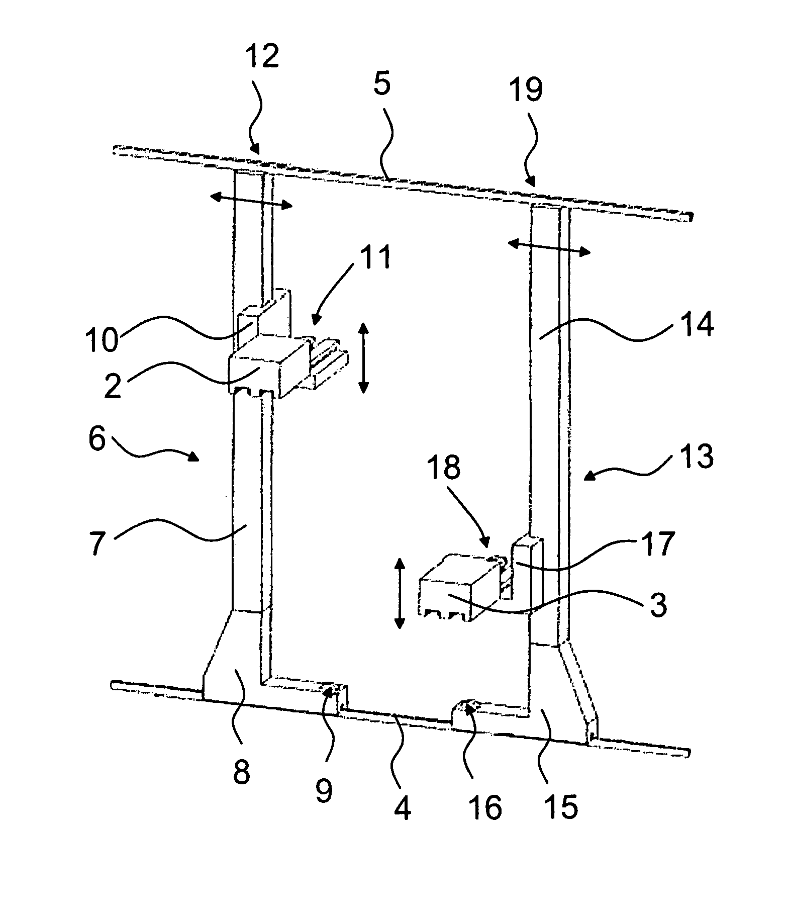
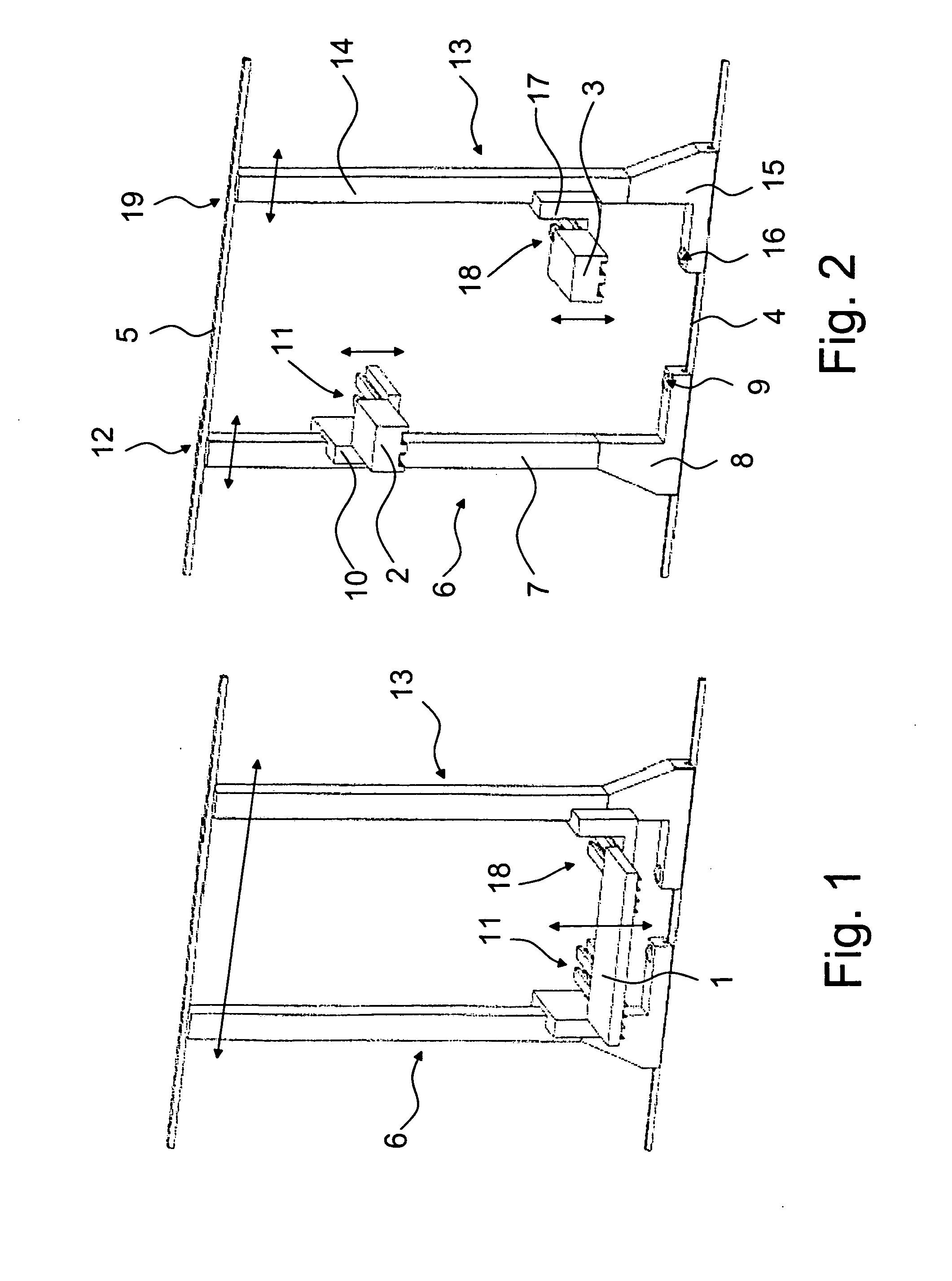
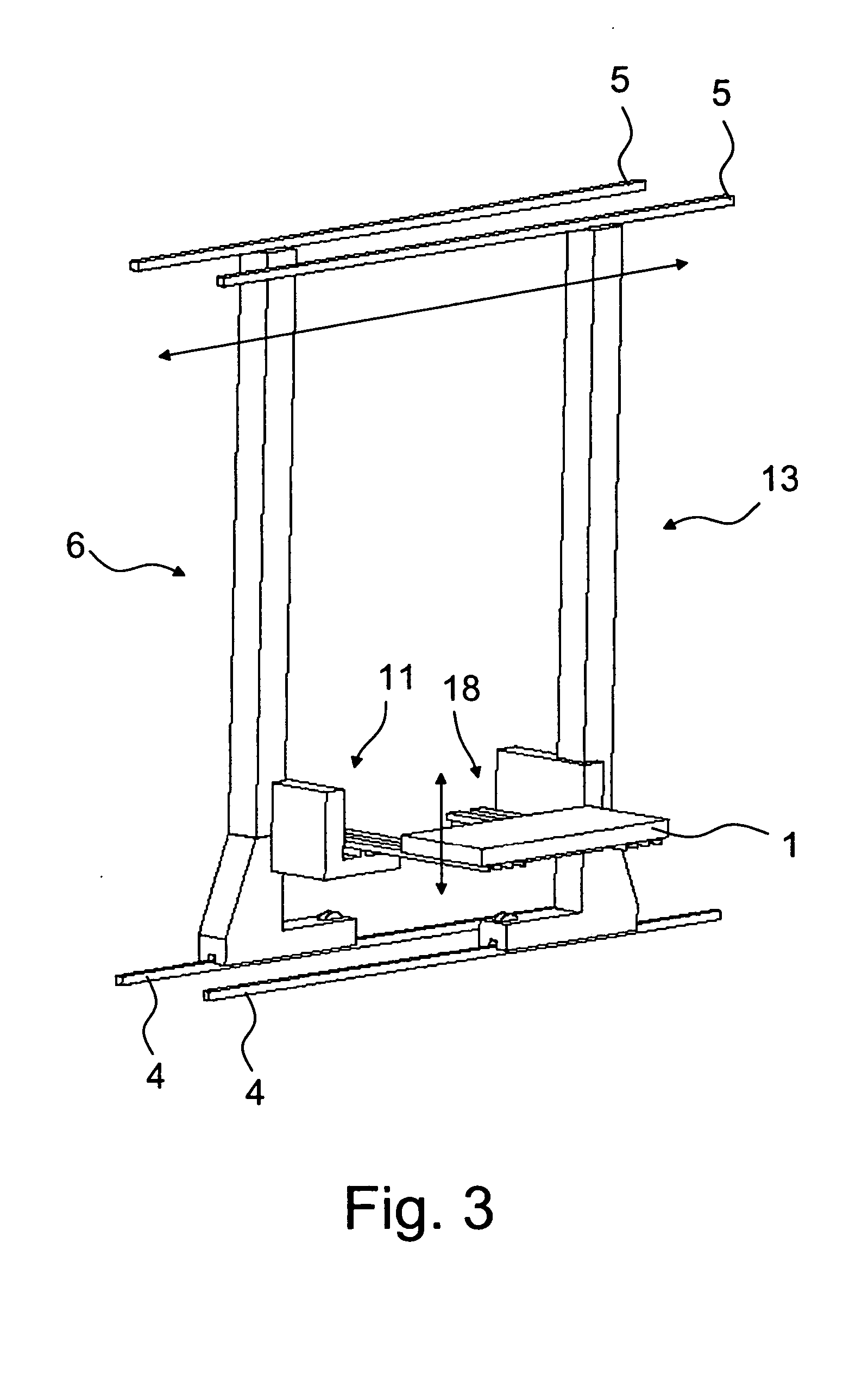
[0021] The stacker cranes 6 and 13 shown in FIGS. 1 and 2 move in a way known as such, either at one set of racks or in an aisle formed between two sets of racks. The structure of the storage racks can be implemented and dimensioned in a variety of ways which are known as such from the design of warehouses for goods of both short and long dimensions. The stacker crane 6 or the stacker crane 13, or both of them, can also operate in different aisles in the way shown in FIG. 2, but one of them, or both of them, move into the same aisle or next to the same rack to operate in the way shown in FIG. 1. The aisles and the storage racks are parallel to a driving rail 4 and extend almost to the level of a guide rail 5, being distributed in several vertical rows and normally also several horizontal rows.

[0022] In this case, the stacker cranes of FIG. 2 are of the same type; the only difference may be whether the forks move in both directions or in a given direction. Stacker cranes of differen...


PUM


Abstract

A method and a system utilizing the same, comprising two or more stacker cranes, of which each is intended to transfer at least one load independently, comprising a horizontally movable driving carriage and a lifting carriage arranged therein and intended for the manipulation and vertical transfer of said load. At least two stacker cranes are arranged to move, when necessary, to such a relative position in which it is possible to manipulate and transfer a load resting on the support of both lifting carriages simultaneously and to perform the movements of the driving carriages and the lifting carriages in a synchronized manner.

Description

CROSS-REFERENCE TO RELATED APPLICATIONS [0001] This application claims priority under 35 USC §119 to Finnish Patent Application No. 20031259 filed on Sep. 4, 2003. FIELD OF THE INVENTION [0002] The invention relates to a system comprising two or more stacker cranes. The invention also relates to a method in the control of a stacker crane system. BACKGROUND OF THE INVENTION [0003] As is well known, for example automatic flexible manufacturing systems and automatic storage systems comprise various feeding points for feeding work pieces into the system for machining, storing or other processing. The work pieces are typically placed on various bases, trays or pallets. Typically, the system also comprises various automatically operating lifting and transfer devices which transfer work pieces from the feeding point to the system, to be processed further or to be stored on a storage rack, and back. The lifting and transfer devices include, for example, stacker cranes which manipulate diffe...

Claims


Application Information

Patent Timeline
Patent Type & Authority Applications(United States)
IPC IPC(8): B65G1/04B66F9/07
CPCB65G1/0407B66F9/07B65G1/0421
Inventor KANTOLA, JUHANANURMINEN, MATTIRANTALAINEN, JUHANIRAPILA, TEROTIKKALA, JARI
Owner FASTEMS
Why Eureka
Try Eureka