Self-tuning ultrasonic meter

a technology of ultrasonic meters and transceivers, applied in the direction of liquid/fluent solid measurement, volume flow testing/calibration, instruments, etc., can solve the problems of accurate measurement of flight time, misidentification of correct zero crossing, and subject to measurement errors

Inactive Publication Date: 2005-03-10
MICRO MOTION INC
View PDF4 Cites 49 Cited by
  • Summary
  • Abstract
  • Description
  • Claims
  • Application Information

AI Technical Summary

Benefits of technology

One expression of the invention is a method to correct for errors in transit time measurements for ultrasonic signals. This method includes the steps of measuring times of flight for ultrasonic signals in a pipeline containing a fluid flow and calculating at least one diagnostic for the ultrasonic signals. At that time, the diagnostic(s) is compared to a set of one or more respective expected values to determine whether the values for the diagnostic is less than, equal to, or greater than the respective expected value. It can then be determined whether one or more errors exist in the times of flight, identifying the errors if they exist, and adjusting the set of expected values.
It is not necessary that each feature or aspect of the invention be used together or in the manner explained with respect to the disclosed embodiment. The various characteristics described above, as well as other features and aspects, will be readily apparent to those skilled in the art upon reading the following detailed

Problems solved by technology

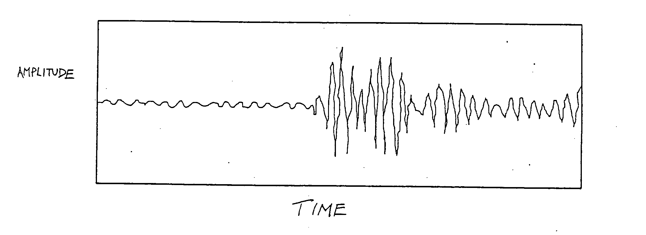
A difficulty that arises in measuring a time of flight exactly is defining when an ultrasonic waveform is received.
However, signal degradation due to pressure fluctuations or the presence of noise may cause the correct zero crossing to be misidentified, as shown in FIG. 3 (not to scale).
Other methods for identifying arrival time may also be used, but each is also subject to measurement error by misidentification of the proper arrival time.
Although the problem of misidentification of an arrival time for an ultrasonic signal has long been known, previous approaches to identifying the instant of arrival for an ultrasonic signal are inadequate.

Method used


Image

  • Self-tuning ultrasonic meter
  • Self-tuning ultrasonic meter
  • Self-tuning ultrasonic meter

Examples


Embodiment Construction

The following describes a method and associated ultrasonic meter to identify errors in transit time measurements and, if errors are present, to tune the meter for optimum performance. The invention identifies and corrects for these time-of-flight measurement errors and distinguishes them from other problems that may be present in the fluid flow. The identity of these other problems may be brought to the attention of a user or operator.

An ultrasonic meter is working correctly if it is making a consistently accurate transit time measurement. It is therefore necessary to determine whether the meter is: 1) always making the correct transit time measurement; 2) normally making the correct transit time measurement; 3) sometimes making the correct transit time measurement; or 4) not making the correct transit time measurement at all.

The inventive ultrasonic meter differs from past ultrasonic meters by its unique analysis of various diagnostics, and by either self-tuning the affected o...


PUM


Abstract

A method and related ultrasonic meter identify and correct for transit time errors such as peak switch errors. The method includes calculating values for a set of diagnostics from measurements of the fluid flow, including transit time measurements. Based on the values for the diagnostics, and whether and how they fall outside of their respective ranges, the meter can identify a variety of problems with the meter or fluid flow, such as whether there has been an intermittent peak switch, a permanent peak switch, or the presence of noise, velocity pulsation in the fluid flow, temperature stratification, or other problem. In the event there is a problem with the meter, the meter self-tunes in order to minimize the chances of the problem happening again.

Description

CROSS-REFERENCE TO RELATED APPLICATIONS Not Applicable. STATEMENT REGARDING FEDERALLY SPONSORED RESEARCH OR DEVELOPMENT Not Applicable. BACKGROUND OF THE INVENTION 1. Field of the Invention A disclosed embodiment of the invention relates generally to the detection of errors in ultrasonic transit time measurements. More particularly, a disclosed embodiment of the invention relates to the identification of mistakes in peak selection and other errors for the ultrasonic meter, with another aspect of the invention relating to a method for correction of ultrasonic meter measurement errors. 2. Description of the Related Art After a hydrocarbon such as natural gas has been removed from the ground, the gas stream is commonly transported from place to place via pipelines. As is appreciated by those of skill in the art, it is desirable to know with accuracy the amount of gas in the gas stream. Particular accuracy for gas flow measurements is demanded when gas (and any accompanying liquid...

Claims


Application Information

Patent Timeline
Patent Type & Authority Applications(United States)
IPC IPC(8): G01D3/08G01F1/66G01F1/72G01F25/00
CPCG01D3/08G01F25/0007G01F1/72G01F1/667G01F25/10G01F25/15
Inventor FREUND, WILLIAM R. JR.ZANKER, KLAUS J.MURRAY, GAIL P.
Owner MICRO MOTION INC
Why Eureka
Try Eureka