Walk-in refrigeration unit control and monitoring system

Inactive Publication Date: 2005-03-17
GINGRAS JEAN PIERRE
View PDF7 Cites 24 Cited by
  • Summary
  • Abstract
  • Description
  • Claims
  • Application Information

AI Technical Summary

Benefits of technology

[0011] According to another broad aspect of the present invention, there is provided a walk-in refrigeration unit comprising: a temperature probe located inside said unit for obtaining a temperature reading inside said unit; a door frame havi

Problems solved by technology

Advances in microprocessors and associated technologi

Method used


Image

  • Walk-in refrigeration unit control and monitoring system
  • Walk-in refrigeration unit control and monitoring system
  • Walk-in refrigeration unit control and monitoring system

Examples


Embodiment Construction

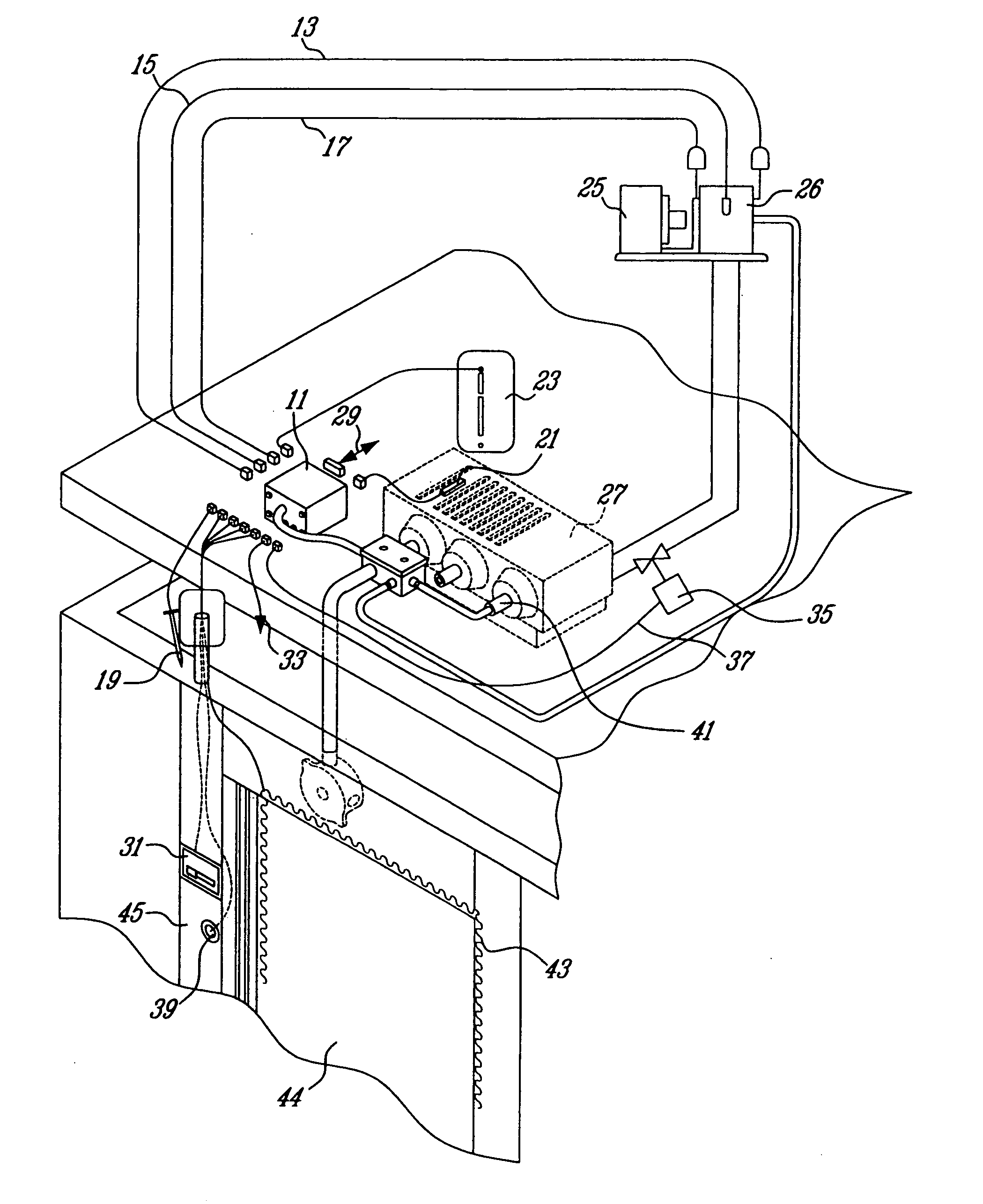
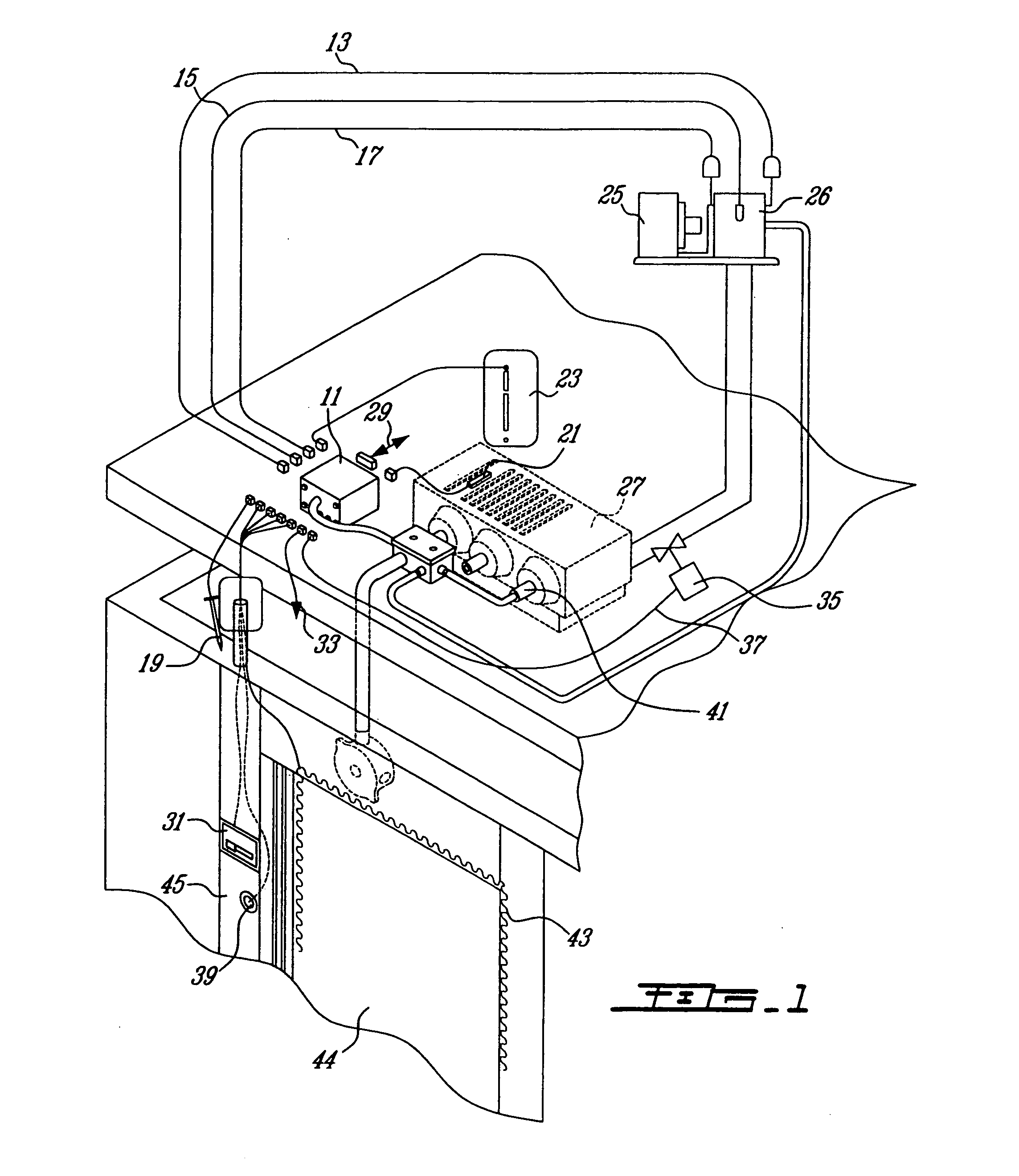
[0014] The preferred embodiment of the present invention will be described with reference to FIGS. 1 and 2. FIG. 1 illustrates a walk-in refrigerator unit according to the preferred embodiment of the present invention. In a cold room environment, such as the one provided by the walk-in refrigeration unit, there are different ways to control and to monitor the temperature, including mechanical devices and electronic controls.

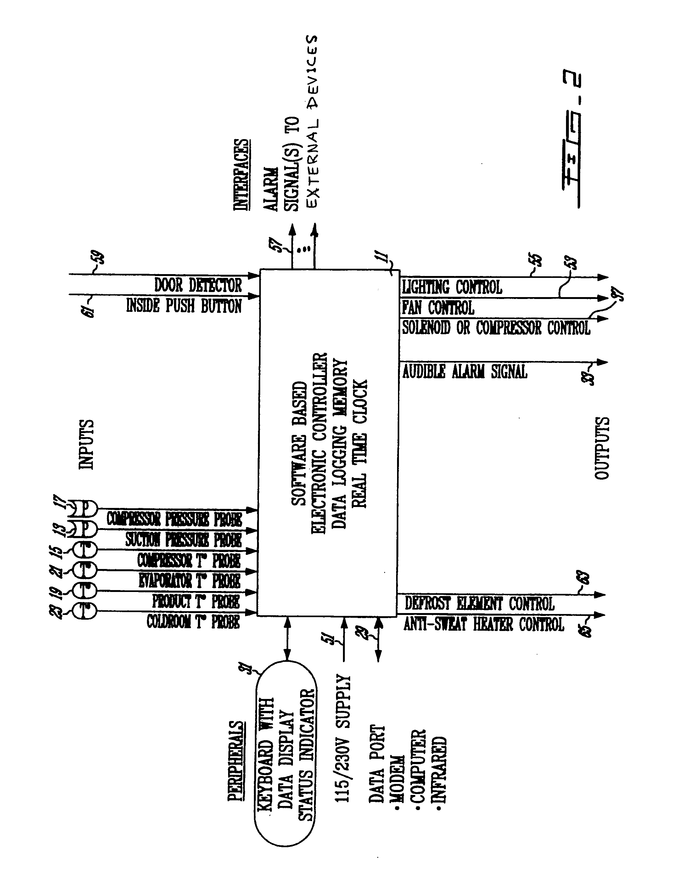
[0015] The software-based electronic controller 11 is the unit that controls the walk-in refrigeration system by constantly monitoring its functioning. The refrigeration system of the walk-in refrigeration unit is completely managed by the electronic controller 11, whose functions include temperature regulation, defrost cycles and evaporator fan motor 41 interruptions. The electronic controller 11 is in communication with a heat exchange unit, which comprises a condenser 25, a compressor 26, an evaporator unit 27 and a solenoid valve 35.

[0016] The compressor 26...


PUM


Abstract

A method for monitoring and controlling of a walk-in refrigeration unit is provided. The method comprises setting at least one of a threshold and timing control values associated to operating modes of the refrigeration unit, receiving at a controller unit operating parameters representative of a condition of at least one of an accessory unit, an environment and a heat exchange unit and controlling a functioning of at least one of the accessory unit and the heat exchange unit according to the control values and the received operating parameters. Other features include communication and data logging capabilities.

Description

CROSS-REFERENCE TO RELATED APPLICATIONS [0001] This application claims priority under 35USC§120 of U.S. patent application Ser. No. 10 / 781,853, filed on Feb. 20, 2004 and which claims priority under 35USC§119(e) of U.S. provisional patent application 60 / 448,493, filed on Feb. 21, 2003 and which also claims priority under 35USC§119(a)-(d) of Canadian patent application 2,419,647, filed on Feb. 21, 2003, the specifications of which are hereby incorporated by reference.FIELD OF THE INVENTION [0002] The present invention relates to a walk-in refrigeration unit control and monitoring method and system. BACKGROUND OF THE INVENTION [0003] The device described in U.S. Pat. No. 6,401,466 B1 (hereby incorporated by reference) is a good example of the present state-of-the-art in the field of walk-in refrigeration units. Many improvements can be made to such existing devices to render walk-in refrigeration units more efficient. [0004] In order to answer today's needs in food safety programs suc...

Claims


Application Information

Patent Timeline
IPC IPC(8): F25D13/00F25D21/00F25D21/04F25D27/00F25D29/00
CPCF25B2600/02F25D2700/16F25B2700/1933F25B2700/2115F25B2700/2116F25D13/00F25D21/002F25D21/04F25D27/005F25D29/00F25D29/008F25D2400/361F25D2700/02F25D2700/10F25D2700/12F25B2700/1931
Inventor GINGRAS, JEAN-PIERRE
Owner GINGRAS JEAN PIERRE
Why Eureka
Try Eureka