Combination radiant/convection gas cooking appliance

Active Publication Date: 2005-03-17
MAYTAG
View PDF14 Cites 20 Cited by
  • Summary
  • Abstract
  • Description
  • Claims
  • Application Information

AI Technical Summary

Benefits of technology

[0008] In a preferred embodiment, the cooking system is positioned below a central opening arranged on the bottom wall of the oven cavity. More specifically, arranged about the central opening are a plurality of convection air vents adapted to direct a convective airflow from the cooking system into the oven cavity. In the most preferred embodiment, a glass panel, preferably CERAN glass, is positioned across the central opening. In this preferred embod

Problems solved by technology

Obviously, this additional ductwork adds to the overall cost and complexity of the appliance, while also occupying space potentially available for other advantageous features.
Furthermore, by transporting heated air through lengthy ducting, the effic

Method used


Image

  • Combination radiant/convection gas cooking appliance
  • Combination radiant/convection gas cooking appliance
  • Combination radiant/convection gas cooking appliance

Examples


Example

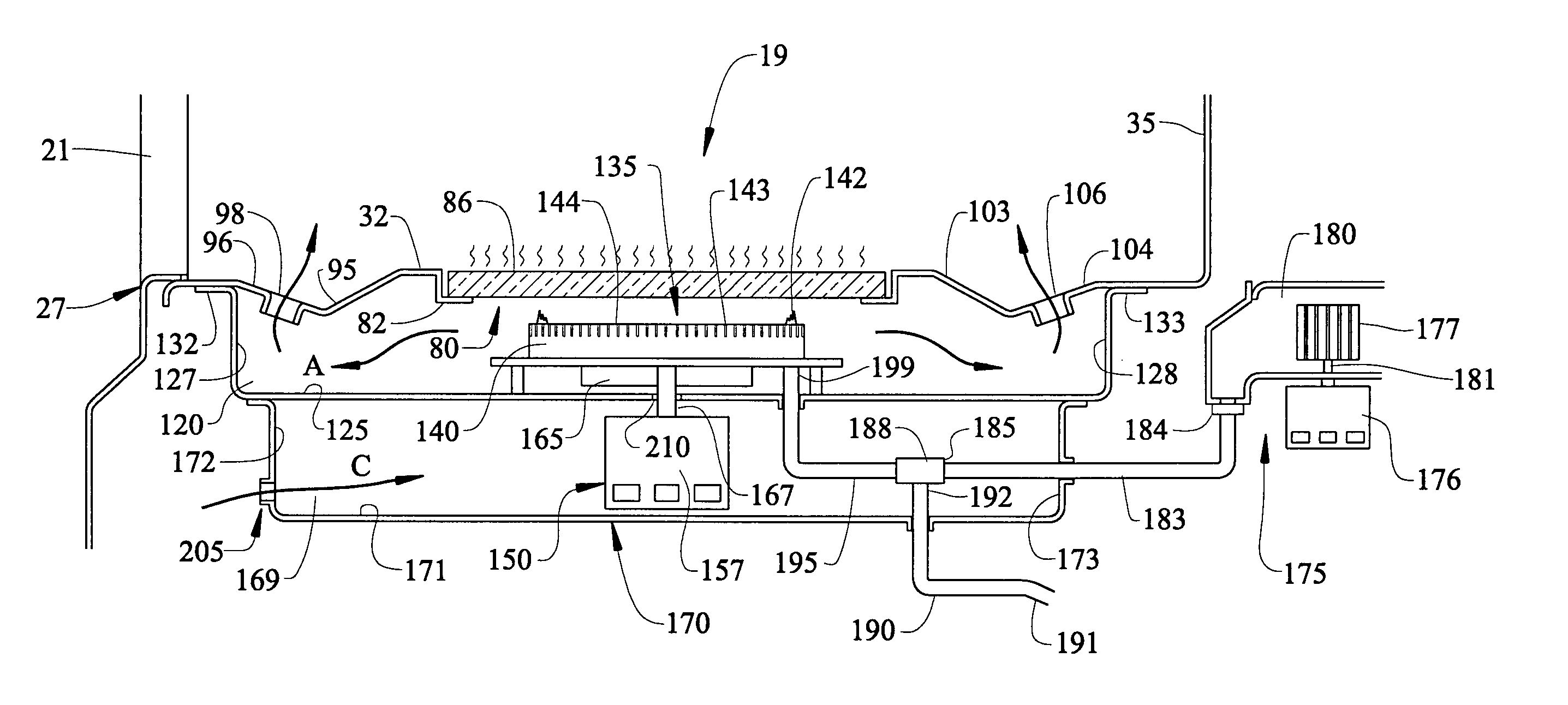
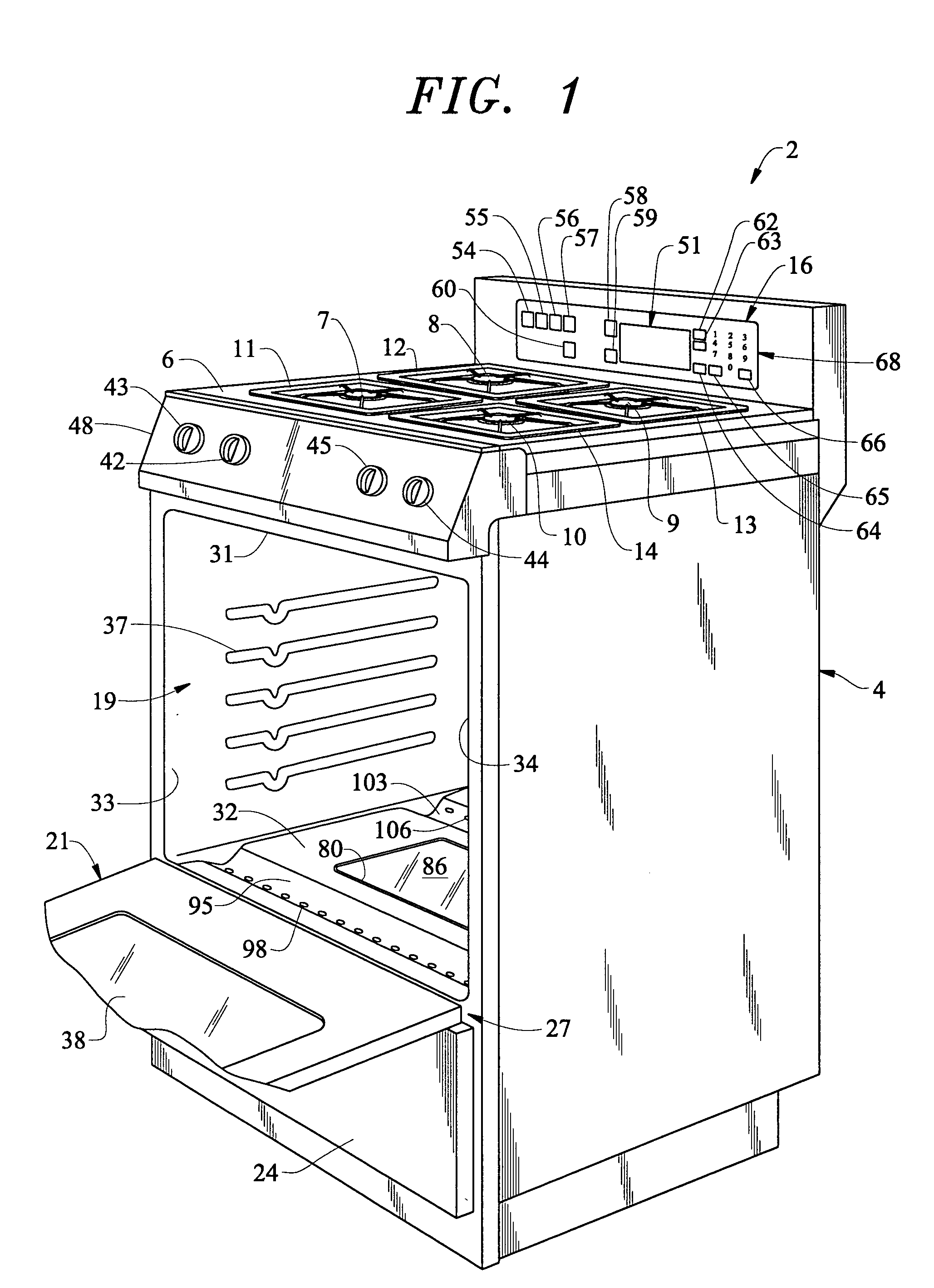
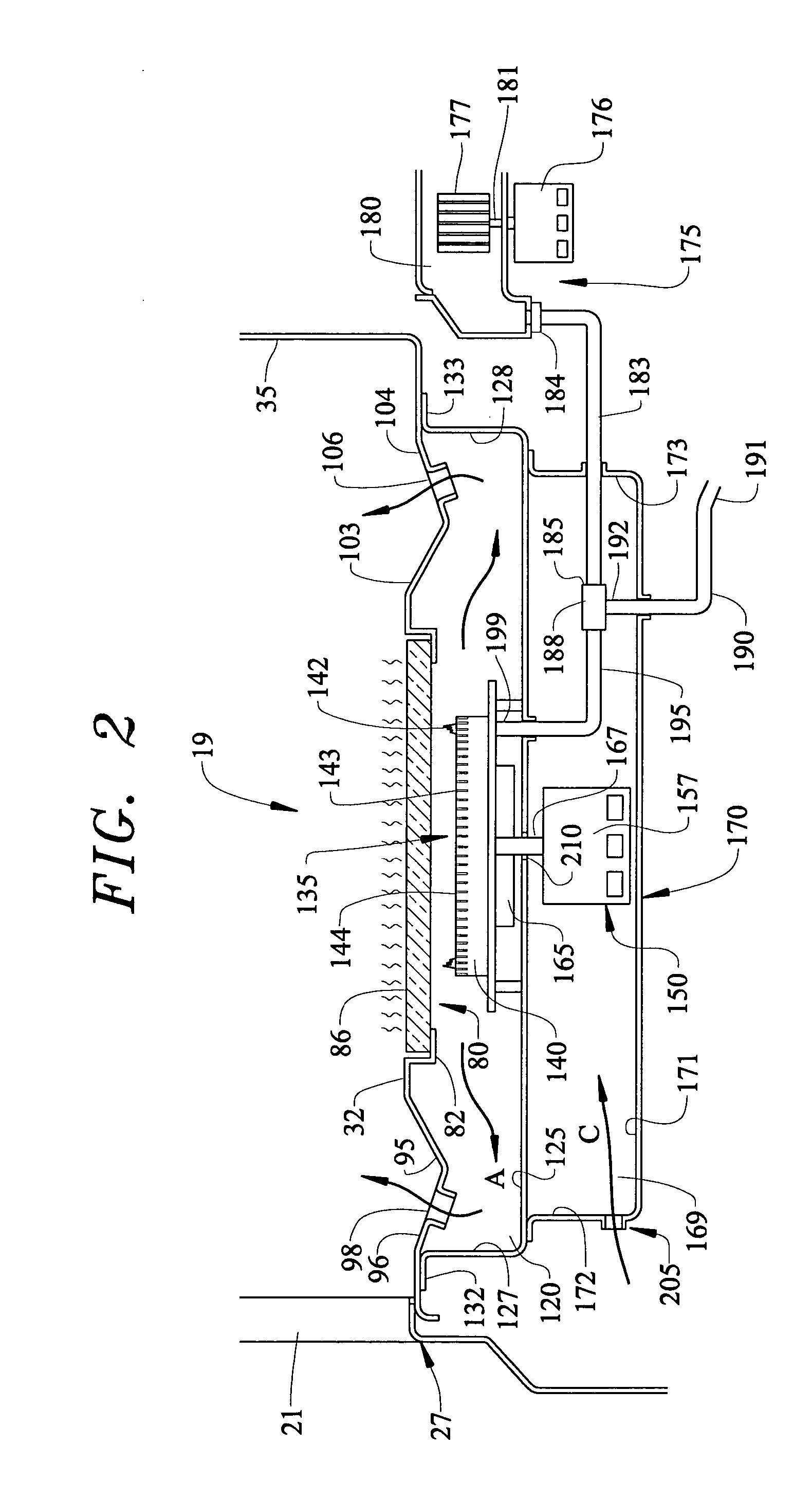
[0012] With initial reference to FIG. 1, a cooking appliance 2 taking the form of a range includes a cabinet shell 4 provided with a cooktop 6. As illustrated, cooktop 6 is provided with a plurality of gas heating elements 7-10 having a corresponding plurality of gas burner grates 11-14. At this point, it should be noted that, although appliance 2 is shown to constitute a free standing gas range, the invention is equally applicable to various other types of types of gas ovens, including slide-in ranges, wall ovens and the like.

[0013] In a manner known in the art, gas cooking appliance 2 includes a control panel 16, an interior oven cavity 19 having an associated door 21, and a lower drawer or bin 24. More specifically, drawer or bin 24 is adapted to be slid into and out of cabinet shell 4 in order to access an interior storage compartment (not shown) arranged therein. As illustrated, door 21 is adapted to pivot at a lower portion 27 to enable selective access to within oven cavity ...


PUM


Abstract

A gas cooking appliance includes a combination radiant/convection cooking system mounted below a bottom wall portion of an oven cavity. The combination cooking system includes a gas burner in the form of a ring element having a central portion within which is positioned a convection fan. In addition to the convection fan, a forced air combustion fan supplies a combustion airflow to the gas burner. The oven preferably includes a glass panel arranged in a bottom wall portion of the oven cavity, above the gas burner. Arranged about the central opening are a plurality of vented openings for introducing the convective airflow into the oven cavity. The glass panel provides both a conductive heat surface transmitting at least a portion of the radiate heat energy into the oven cavity and a viewing surface allowing a consumer to view the operation of the gas burner.

Description

BACKGROUND OF THE INVENTION [0001] 1. Field of the Invention [0002] The present invention pertains to the art of cooking appliances and, more particularly, a gas cooking appliance including a combination radiant / convection cooking system employing a gas burner located below a glass panel arranged along a bottom wall of an oven cavity. [0003] 2. Discussion of the Prior Art [0004] In general, combining convection and radiant cooking is well known in the art of gas cooking appliances. In typical arrangements, a convection fan or blower is mounted on a top or rear wall of an oven cavity, while a gas burner is mounted along a bottom wall. With this arrangement, the gas burner radiates heat into the oven cavity while, at the same time, heats an airflow directed into the oven cavity by the convection blower. [0005] Using this construction, in addition to ductwork required for combustion, cooling and exhaust air associated with the gas burner, additional ductwork is needed to carry the heat...

Claims


Application Information

Patent Timeline
IPC IPC(8): F24C15/32
CPCF24C15/322
Inventor LEVI, DAVID E.PICKERING, MARK A.SMITH, LLOYD A. JR.
Owner MAYTAG
Why Eureka
Try Eureka