Jig for forming a box joint

a box joint and joint technology, applied in the field of joints for cutting wood, can solve the problems of adding to the limitations of the joints, wasting wood, and all the complexity of the cutting of the joints

Inactive Publication Date: 2005-03-17
FREIDLUND PAUL
View PDF18 Cites 21 Cited by
  • Summary
  • Abstract
  • Description
  • Claims
  • Application Information

AI Technical Summary

Benefits of technology

[0010] Also advantageously, the present invention provides for alignment of the boards such that the router may be moved in a straight line from one board to the next and route the boards at the correct location.

Problems solved by technology

Typically, these joints all suffer from complexity of cutting.
If the jig is not set up correctly between the pairs of boards, wood is wasted and the process is continued until the cuts are at the right location.
Moreover, these jigs typically have a maximum size of board that can be used with the jig further adding to their limitations.

Method used


Image

  • Jig for forming a box joint
  • Jig for forming a box joint
  • Jig for forming a box joint

Examples


Embodiment Construction

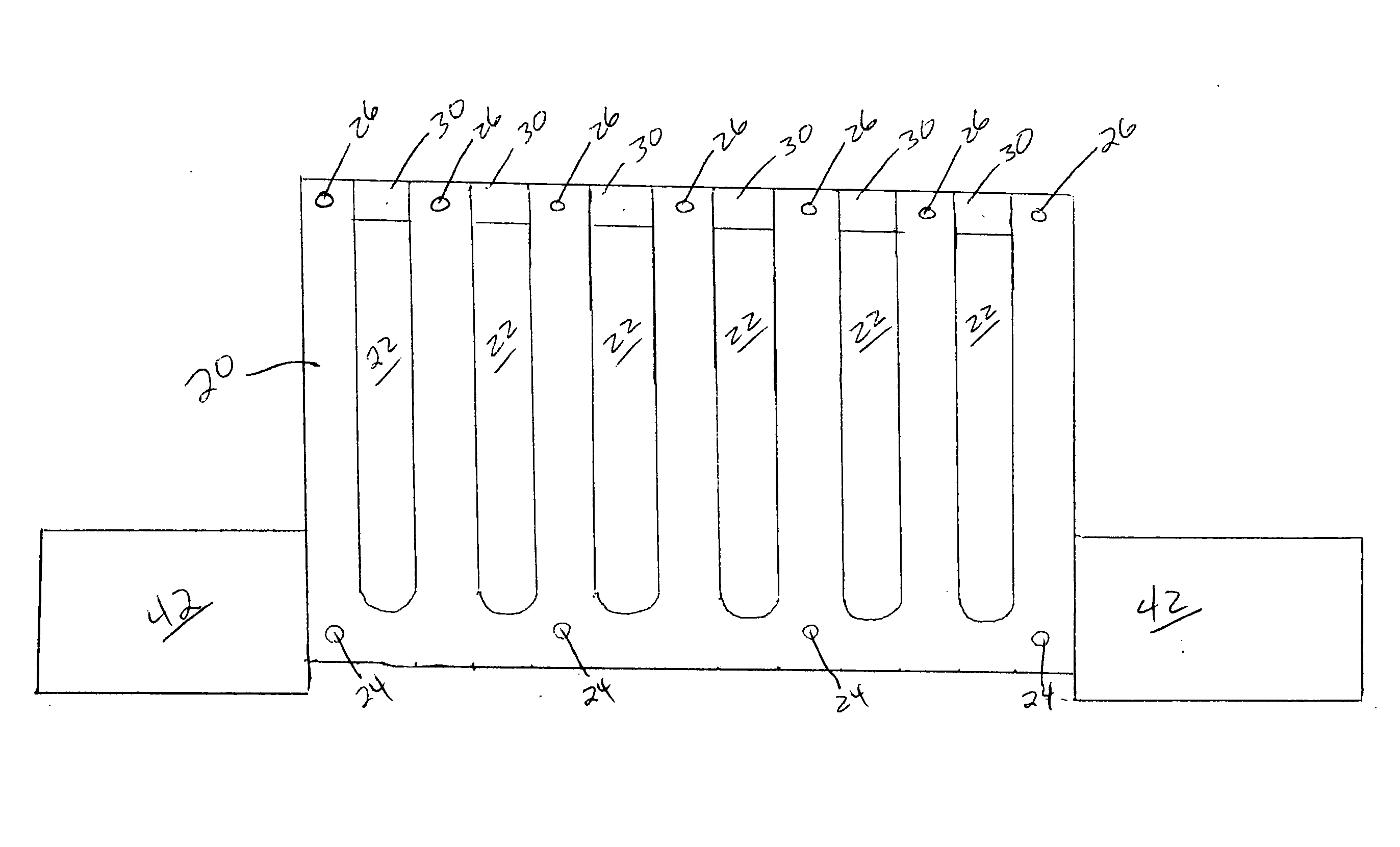
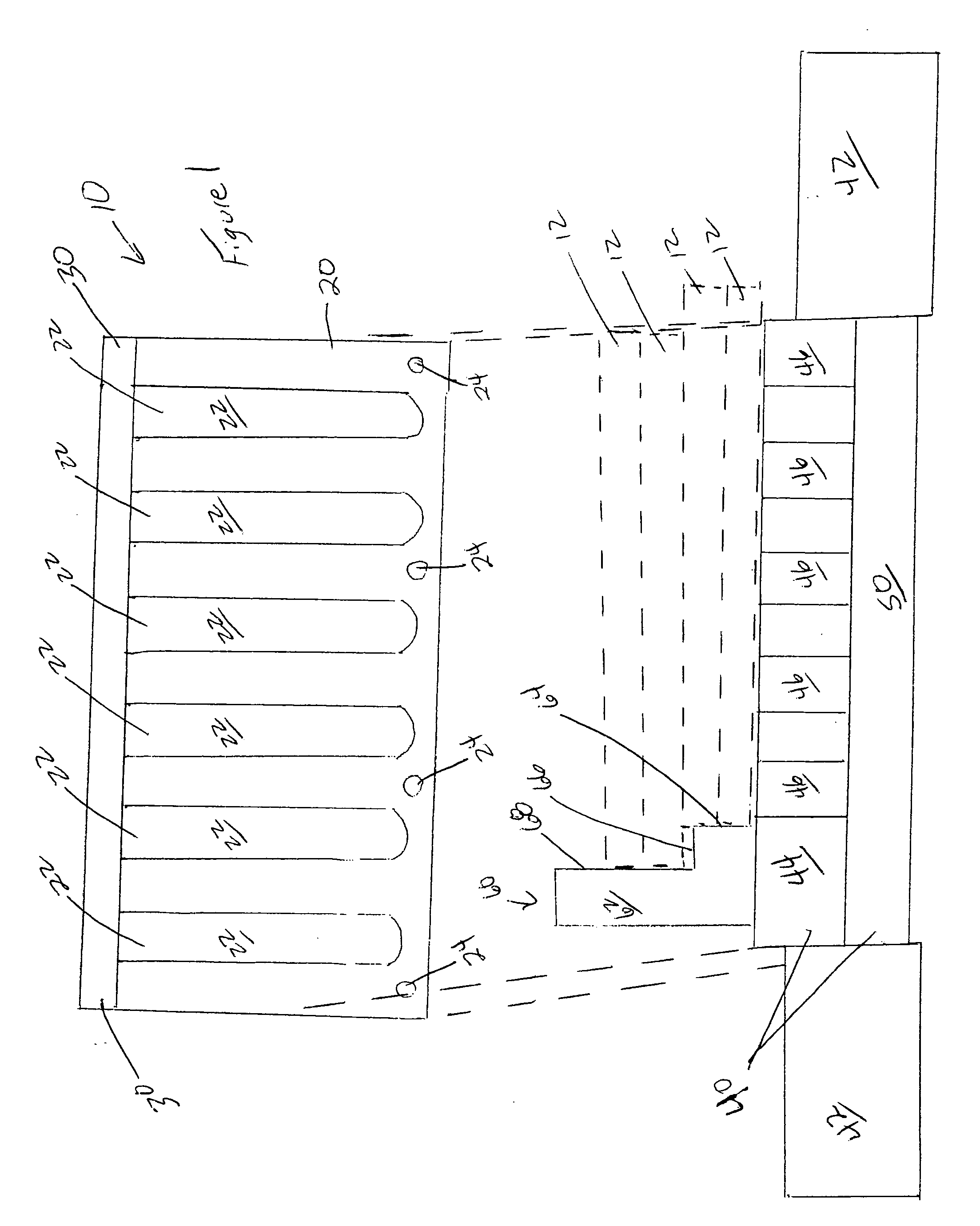
[0024] The box joint jig 10 may include a bottom plate 20, a front plate 30, a back plate 40, a back alignment member 60, a bottom alignment member 80, a router bit 90 and an adapter 92. The jig 10 is used for forming box joints 14 as shown in FIG. 7. The jig 10 simultaneously orients four boards 12 and guides the router bit 90 such that the router bit 90 cuts the routes 16 for all four boards 12 in a single sweep. These components are discussed in serial fashion below.

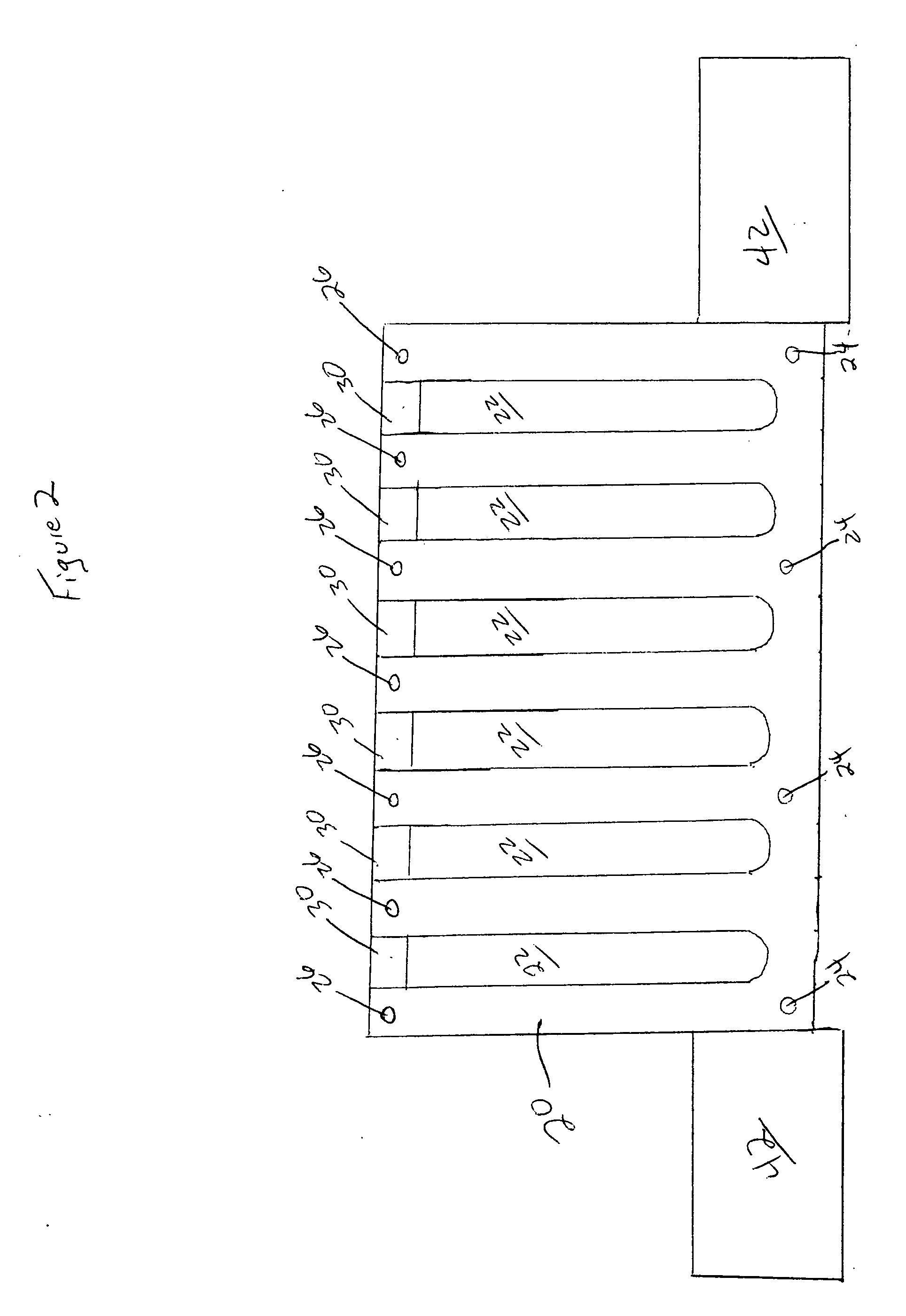
[0025] The bottom plate 20 may be joined to the front plate 30 and back plate 40. (See FIGS. 1 and 2). The plates 20, 30 and 40 may be joined with fasteners 24 and 26 respectively, may be cast, molded or otherwise formed integrally, or may be joined in any other manner known in the art. The bottom plate 20 defines grooves 22, which extend through the bottom plate 20 and provide access for the router bit to boards 12 positioned atop the bottom plate 20.

[0026] The bottom plate 20 may be interchangable with other botto...


PUM


Abstract

A box joint jig, including a bottom plate; a back plate joined to the bottom plate; and an alignment member the alignment member structured to orient four boards positioned adjacent the bottom plate for a router and a method of forming a box joint, including the steps of mounting four boards in a jig; routing the boards through a groove; routing the boards through additional grooves; dismounting the boards; and joining the corners of the boards interlacing the routes cut in the boards.

Description

BACKGROUND OF THE INVENTION [0001] The present invention relates to jigs for cutting wood and related products and more specifically to jigs used to form box joints with a router. [0002] Jigs have long been used to make repetitive cutting simpler. In a typical jig, boards or other material to be cut are uniformly laid on a jig and marked or cut at a specific location. For instance studs to be cut to a certain length may all be abutted along a straight edge. A marker of some form may be positioned at the distance away from the straight edge at which the cut is to be made. Without measuring any of the boards, the woodworker knows where to make the cut across all the boards, e.g., at the point of the marker. Jigs in essence remove the need for repeated measuring. [0003] Various complex joints have been proposed and used for joining adjacent corners of furniture. The dove tail, box joint and many other varieties of joints have been developed in this regard. Each type of joint has certai...

Claims


Application Information

Patent Timeline
Patent Type & Authority Applications(United States)
IPC IPC(8): B27F1/12
CPCB27F1/12
Inventor FREIDLUND, PAUL
Owner FREIDLUND PAUL
Why Eureka
Try Eureka