
X-ray detector

a detector and x-ray technology, applied can solve the problems of not being particularly robust in the field of x-ray detectors, and achieve the effect of simple production

Inactive Publication Date: 2005-03-17
SIEMENS HEALTHCARE GMBH
View PDF11 Cites 50 Cited by
  • Summary
  • Abstract
  • Description
  • Claims
  • Application Information

AI Technical Summary

Benefits of technology

[0008] An object of an embodiment of the invention is to reduce or even eliminate at least one of the disadvantages of the prior art. One intention of at least one embodiment, in particular, is to provide an x-ray detector which is as simple to produce as possible and is as robust as possible.
[0009] An embodiment of the invention provides that the detector plate is accommodated in the housing in a floating manner by use of at least one damping element. This allows a robust x-ray detector to be provided in a surprisingly simple and low-cost way.
[0010] The housing may be a cassette. In this case, it is possible to produce mobile x-ray detectors in a simple way by using known flat detectors.

Problems solved by technology

The flat detectors known from the prior art are not particularly robust.
Under mechanical loading, for example instances of impact, vibration and the like, they may be destroyed.

Method used


Image

  • X-ray detector
  • X-ray detector
  • X-ray detector

Examples


Embodiment Construction

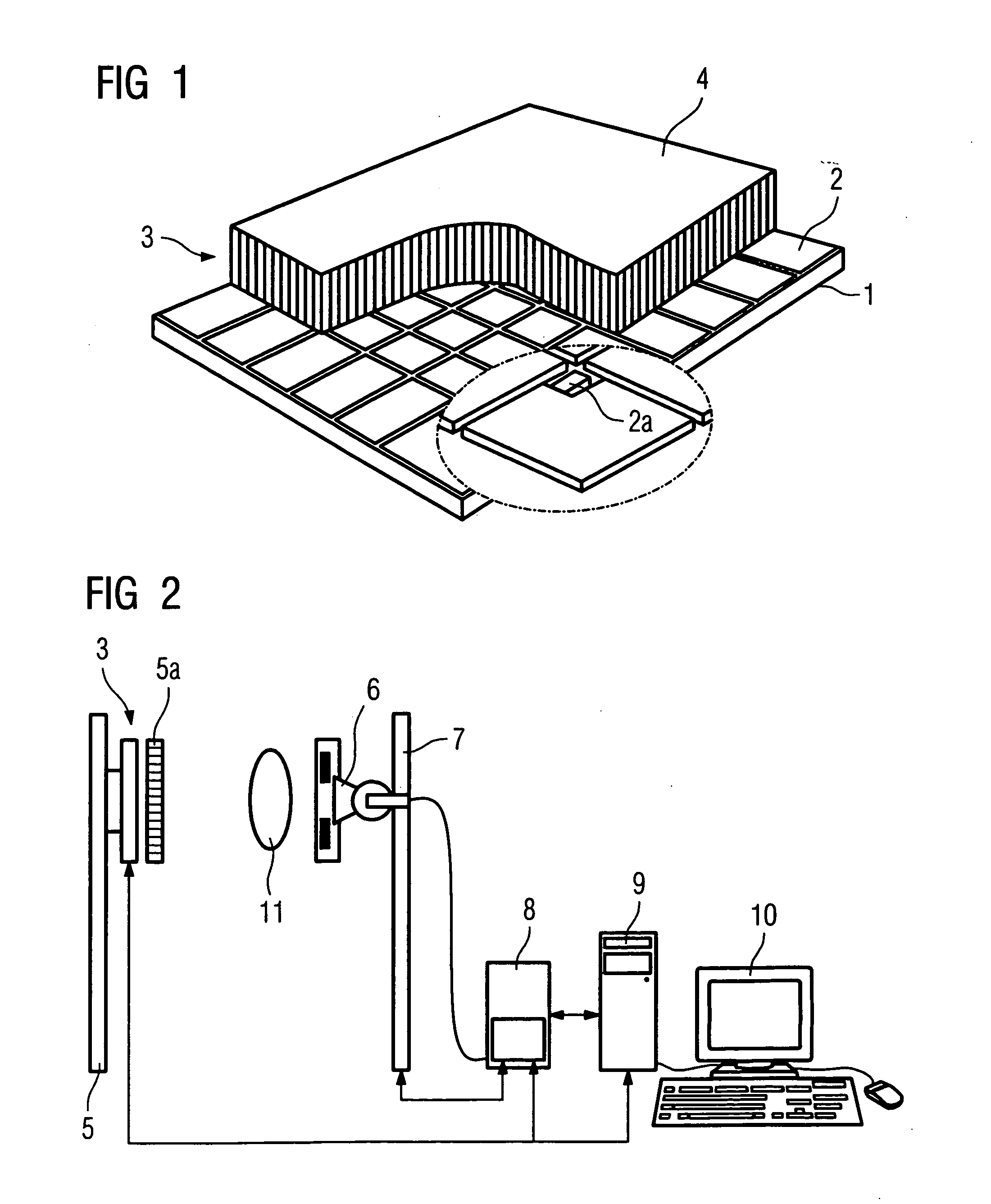
[0027] In the case of the x-ray or flat detector shown in FIG. 1, a multiplicity of detector elements 2 are accommodated on a substrate 1, which is produced for example from glass. The detector elements 2 may be photodiodes produced from amorphous silicon. The detector elements 2 form a matrix in an X direction and a Y direction. Each of the detector elements 2 has a switch 2a. Applied to the detector elements 2 is a converter layer 4, which is produced for example from a luminescent material. This may be, for example, CsJ. The arrangement formed by the substrate 1, the detector elements 2 and the converter layer 4 is referred to hereafter as the detector plate 3.

[0028]FIG. 2 shows a schematic view of an x-ray device according to the prior art, using the x-ray detector shown in FIG. 1. The x-ray detector is fastened to a stand 5. It is accommodated in a housing. Arranged upstream of the x-ray detector on the radiation entry side is an anti-scatter grid 5a. An x-ray source 6 is acco...


PUM


Abstract

An x-ray detector includes a detector plate having a multiplicity of detector elements arranged in the X direction and the Y direction, accommodated in a housing. To increase the robustness, the detector plate is accommodated in the housing in a floating manner by using at least one damping element.

Description

[0001] The present application hereby claims priority under 35 U.S.C. §119 on German patent application numbers DE 103 42 197.1 filed Sep. 12, 2003, and DE 10 2004 022 901.5 filed May 10, 2004, the entire contents of each of which are hereby incorporated herein by reference. FIELD OF THE INVENTION [0002] The invention generally relates to an x-ray detector. BACKGROUND OF THE INVENTION [0003] X-ray detectors are known from Spahn, M. et al., Radiologe 2003, 43:340-350, for example. These are so-called solid-state or flat detectors. Of these, a distinction is made between flat detectors with an indirectly converting converter layer and flat detectors with a directly converting converter layer. [0004] Flat detectors with an indirectly converting converter layer have a detector matrix which is formed by a multiplicity of photodiodes and is produced for example from amorphous silicon. The detector matrix is superposed by a converter layer formed by a scintillator. Incident x-ray radiation...

Claims


Application Information

Patent Timeline
Patent Type & Authority Applications(United States)
IPC IPC(8): A61B6/00G01T1/24G01T1/29G03B42/02H04N5/225H04N5/32H04N5/321H04N7/18
CPCA61B6/00A61B6/4233H04N5/321H04N5/2253G03B42/02H04N23/54
Inventor SPAHN, MARTINSCHMITT, THOMAS
Owner SIEMENS HEALTHCARE GMBH
Features
  • Generate Ideas
  • Intellectual Property
  • Life Sciences
  • Materials
  • Tech Scout
  • Unparalleled Data Quality
  • Higher Quality Content
  • 60% Fewer Hallucinations
Learn More