
Motor control apparatus

a motor control and motor technology, applied in the direction of motor/generator/converter stopper, electronic commutator, dynamo-electric converter control, etc., can solve the problems of high processing ability and high time requirements, and achieve the effect of high processing ability and easy and reliably determining the completion of starting

Inactive Publication Date: 2005-03-17
SANDEN CORP
View PDF7 Cites 7 Cited by
  • Summary
  • Abstract
  • Description
  • Claims
  • Application Information

AI Technical Summary

Benefits of technology

An object of the present invention is to provide a motor control apparatus capable of easily and reliably determining the completion of starting of a synchronous motor, without the need of an arithmetic unit having high processing ability.
According to this invention, when an operation command specifying a predetermined target rotation speed is received in a state where the motor is at rest, the motor is caused to start with the predetermined voltage and voltage phase. After the starting, the motor speed is gradually increased, and when the motor speed reaches a predetermined value lower than the target rotation speed, the completion of starting is determined and a starting operation is changed to a normal operation. Thus, it is enough to determine the completion of starting only once, and thus the determination is easy to perform and reliable. Since the determination of completion of starting does not require an arithmetic unit of high processing ability, the cost of the control apparatus can be reduced.

Problems solved by technology

However, this motor control apparatus entails a drawback that much time is required to determine the completion of starting since the determination must be repeated as long as a variation in the detected phase differences is larger than the predetermined value, and entails a drawback that an arithmetic unit is required to have high processing ability since it has to perform the complicated determination processing.

Method used


Image

  • Motor control apparatus
  • Motor control apparatus
  • Motor control apparatus

Examples


Embodiment Construction

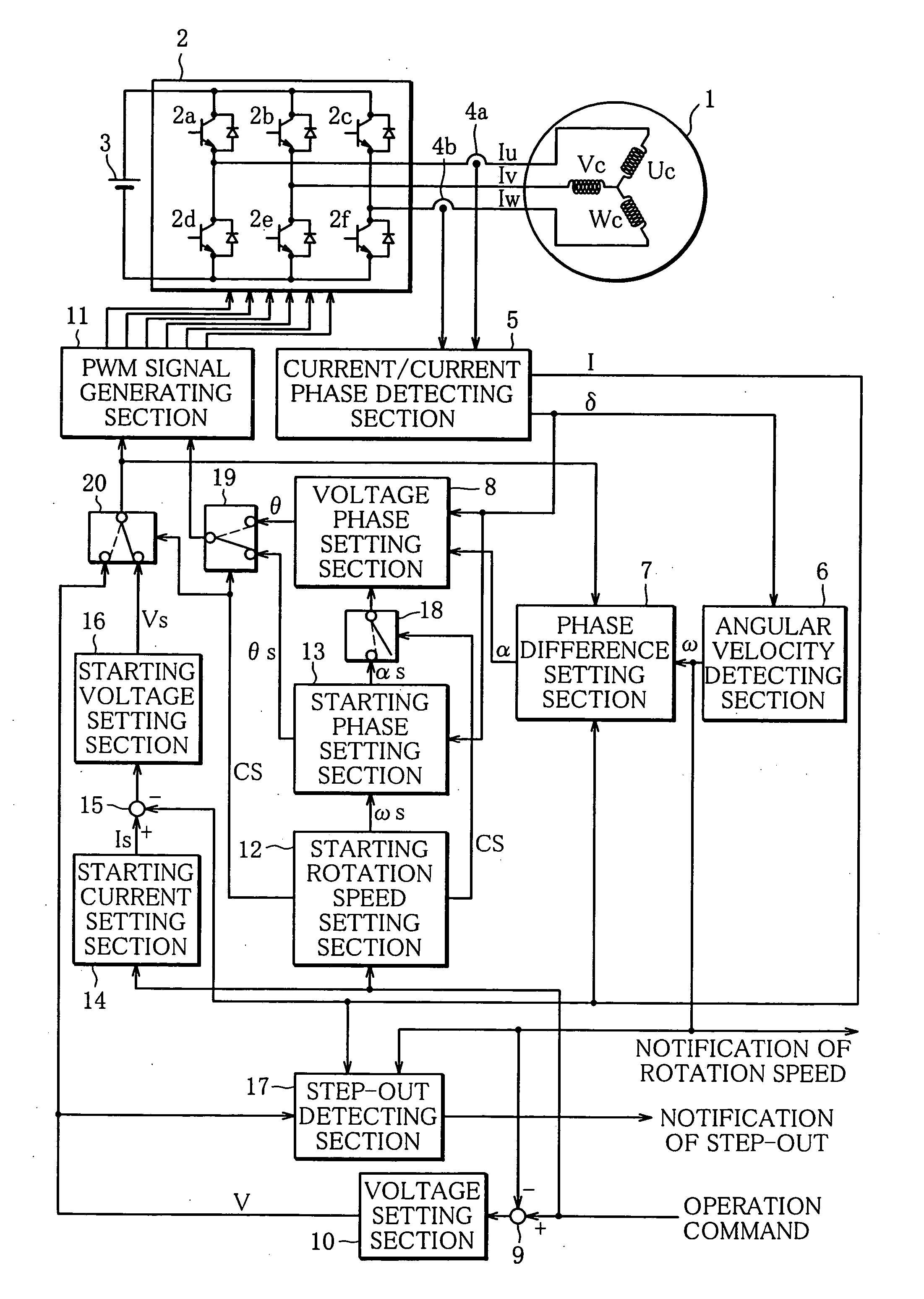
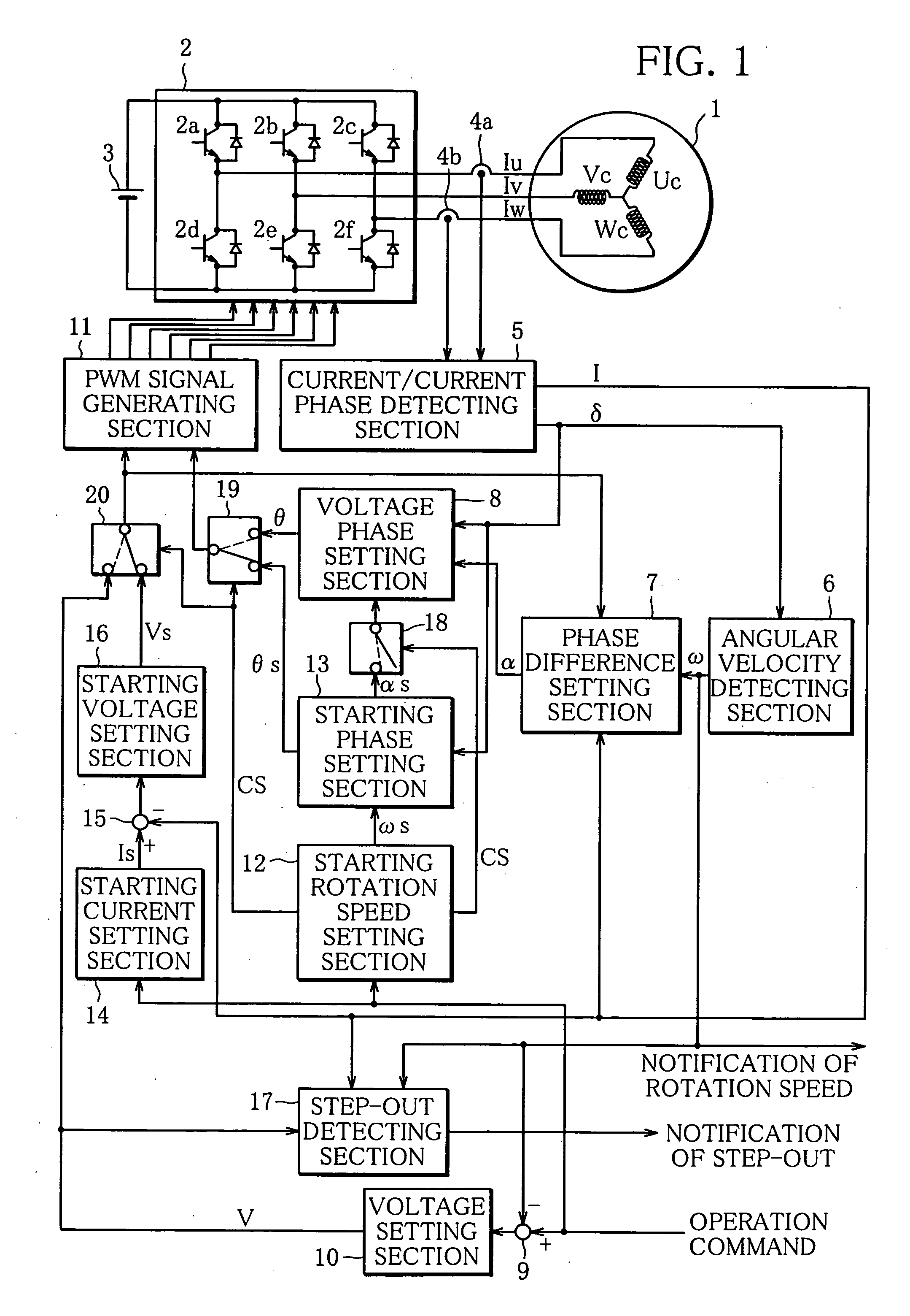
With reference to FIG. 1, a motor control apparatus according to an embodiment of this invention will be explained.

In FIG. 1, a motor 1 is a brushless DC motor comprised of an armature including three phase windings or coils Uc, Vc, Wc and a rotor including a permanent magnet. The motor 1 is rotatably driven by pseudo AC power supplied from an inverter section 2 to the three phase coils Uc, Vc, Wc.

The inverter section 2 comprises three pairs of switching elements 2a, 2d; 2b, 2e; 2c, 2f comprised of IGBTs or the like and connected in parallel with a DC power source 3 that is comprised of a battery or the like. These six switching elements 2a-2f of the inverter section 2 are turned on and off by PWM signals supplied from a PWM signal generating section 11, so as to convert the DC power into pseudo AC power and outputs the AC power to the three phase coils Uc, Vc, Wc of the motor 1.

Current sensors 4a, 4b detect two of the currents flowing through the three phase coils Uc, Vc, Wc...


PUM


Abstract

A motor control apparatus capable of easily and reliably determining the completion of starting of a synchronous motor and not requiring an arithmetic unit having high processing ability for the determination. When an operation command including a predetermined target rotation speed is received in a state where the motor is at rest, PWM signals are created on the basis of a starting voltage set by a starting voltage setting section and a starting phase set by a starting phase setting section, whereby the motor is started. After the start of the motor, a starting rotation speed setting section makes the processing to increase the starting rotation speed. When the starting rotation speed reaches a predetermined value smaller than the target rotation speed, it is determined that the starting is completed, and a shift is made from starting operation to normal operation.

Description

BACKGROUND OF THE INVENTION 1. Field of the Invention The present invention relates to a motor control apparatus that improves the starting process of a synchronous motor used to drive a compressor of an air conditioner or the like. 2. Description of the Related Art Disclosed in JP-A-2001-54295 is a sensorless motor control apparatus that comprises means for detecting electric current flowing through coils of a synchronous motor, means for detecting the phase difference between current and voltage supplied to the coils, and means for detecting completion of starting of the synchronous motor based on the phase difference. In this control apparatus, the phase difference between current and voltage after the start of the synchronous motor is detected, and the detection is repeated while changing the voltage and frequency of electric power supplied to the coils, if a variation in the detected phase differences is larger than a predetermined value. When the variation in phase differe...

Claims


Application Information

Patent Timeline
Patent Type & Authority Applications(United States)
IPC IPC(8): H02P1/46H02P1/52H02P6/06H02P6/08H02P6/17
CPCH02P1/46H02P6/205H02P1/52H02P6/21
Inventor HIRONO, DAISUKE
Owner SANDEN CORP
Learn More