
Battery type determination device and battery-driven electronic device including the same

a type determination and battery technology, applied in electrochemical generators, instruments, transportation and packaging, etc., can solve the problems of insufficient attention, inconvenient operation, and inconvenient use, and achieve the effect of simple configuration and easy and reliable determining the typ

Inactive Publication Date: 2015-06-25
OPTEX CO LTD
View PDF10 Cites 3 Cited by
  • Summary
  • Abstract
  • Description
  • Claims
  • Application Information

AI Technical Summary

Benefits of technology

The present invention aims to provide a battery type determination device that can easily and reliably identify the types of batteries, regardless of their shape or characteristics. This device can be used in battery-driven electronic devices that use multiple types of batteries. The technical effect is the simplification of battery type determination and the improvement of battery usage in electronic devices.

Problems solved by technology

However, in such a conventional case of determining the type of a battery from a voltage or an internal resistance of the battery, a circuit for determining the type of a battery is complicated, and also, power of the battery is consumed in the determination, thus contradicting the purpose of prolonging a battery life.
In addition, in the case of determining the type of a battery based on the shape of the battery, if plural types of batteries are used, it is necessary to prepare a plurality of determination units having structures adapted to the respective shapes of batteries, thus increasing time and effort.
However, these have not been sufficiently addressed.
Further, if the ambient temperature changes, battery voltage also changes.
On the other hand, in the case of battery-driven security sensor, a battery cannot be replaced for a long time in some installation places.
However, in some security sensors, due to control therefore, the types of batteries that can be used are limited.

Method used


Image

  • Battery type determination device and battery-driven electronic device including the same
  • Battery type determination device and battery-driven electronic device including the same
  • Battery type determination device and battery-driven electronic device including the same

Examples


Embodiment Construction

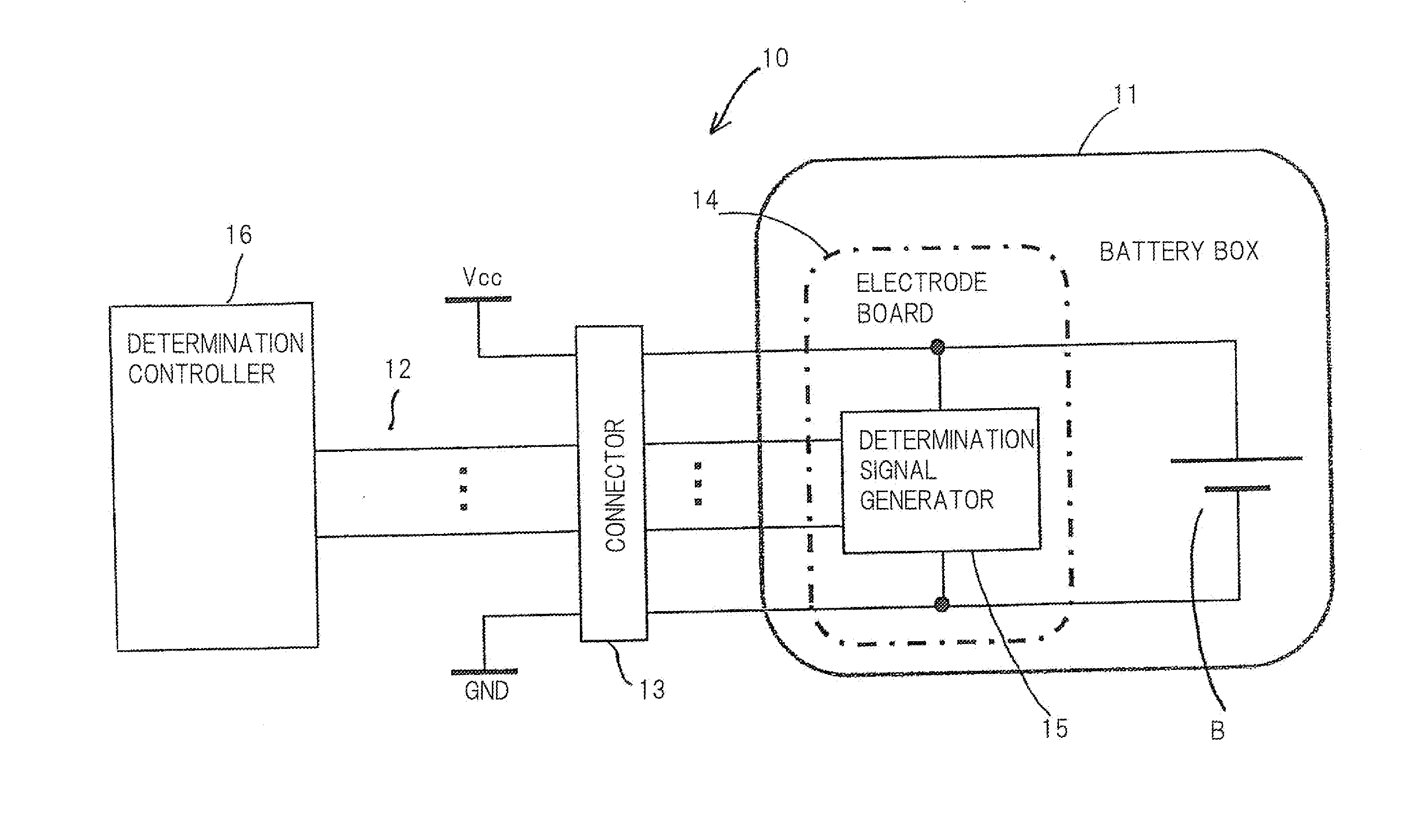
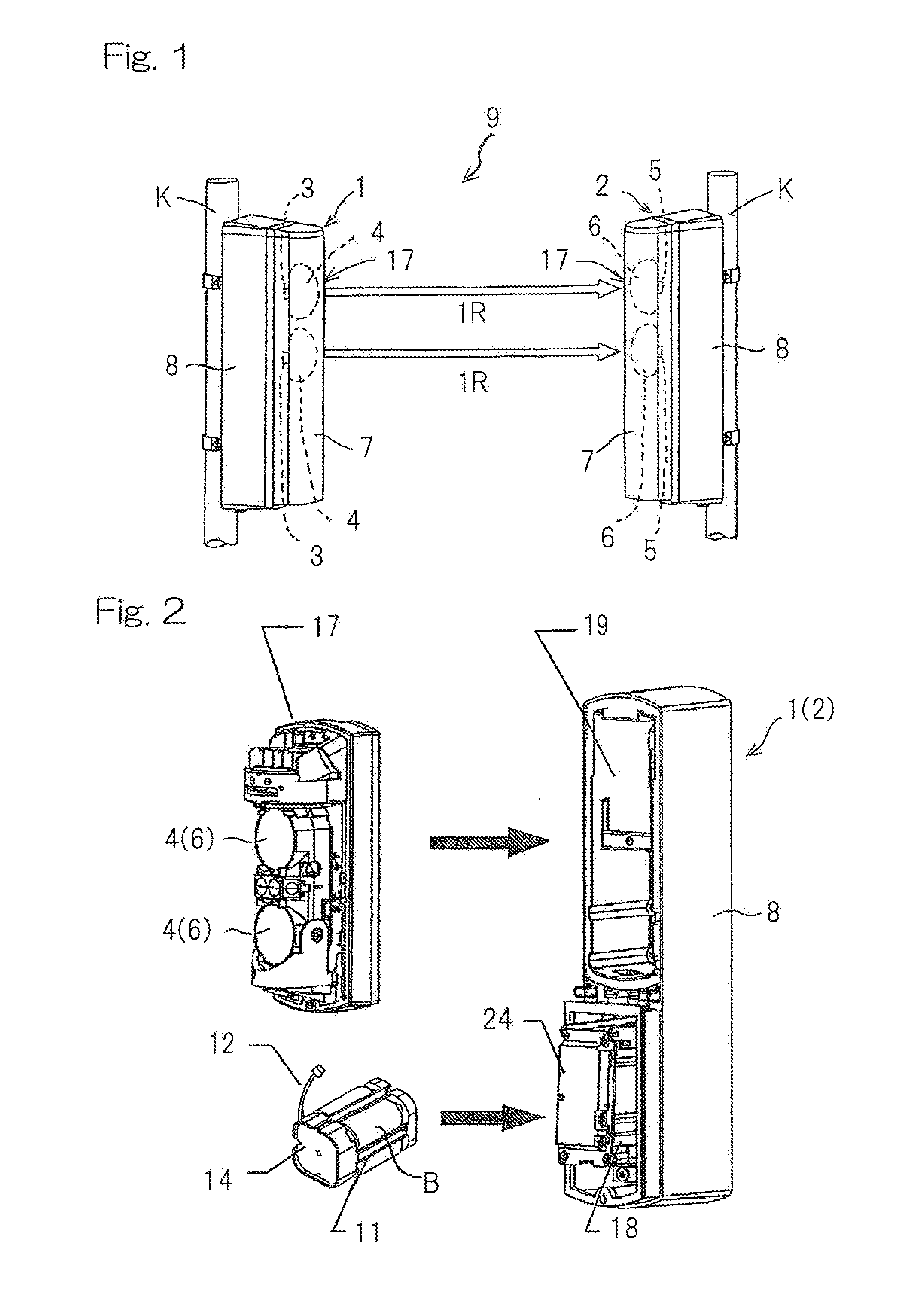
[0027]Hereinafter, embodiments of the present invention will be described with reference to the drawings. FIG. 1 is a perspective view showing a battery-driven security sensor 9 according to a first embodiment of the present invention. FIG. 2 is an exploded perspective view showing the security sensor in FIG. 1. As shown in FIG. 1, the security sensor 9 is, for example, an AIR-type (active infrared ray type) security sensor having a beam projector 1 and a beam receiver 2 which is placed opposite to the beam projector 1 and which has two elements receiving detection beams or rays such as two infrared rays IR emitted from the beam projector 1. The beam projector 1 and the beam receiver 2 are each mounted on a mounting portion K on, such as, a pole or a wall.

[0028]When an infrared ray IR from the beam projector 1 is intercepted by an object, the security sensor 9 detects the object based on change in the signal level of a detection signal (the amount of the infrared ray) received by th...


PUM


Abstract

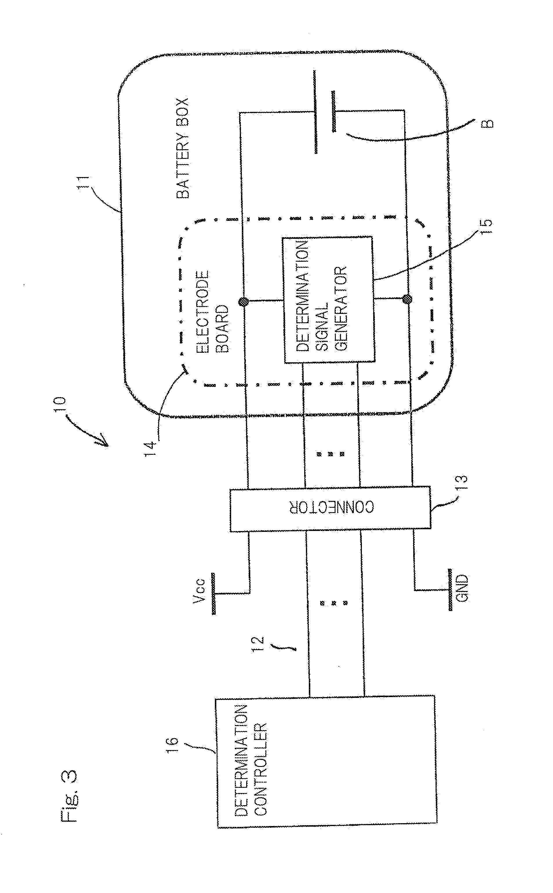
Provided are a battery type determination device with a simple configuration capable of easily and reliably determining the types of a plurality of batteries irrespective of shapes and characteristics of the batteries, and a battery-driven electronic device that includes the battery type determination device and allows usage of plural types of batteries. The battery type determination device is used in a battery-driven electronic device operable with plural types of batteries having different shapes and characteristics, and includes a determination signal generator for generating a determination signal that is allocated for each of the plural types of batteries without depending on shapes and characteristics of the batteries and is formed by combination of binary signals prescribed for each type of battery; and a determination controller for determining the type of each battery based on the generated determination signal.

Description

CROSS REFERENCE TO THE RELATED APPLICATION[0001]This application is based on and claims Convention priority to Japanese patent application No. 2013-263290, filed Dec. 20, 2013, the entire disclosure of which is herein incorporated by reference as a part of this application.BACKGROUND OF THE INVENTION[0002]1. Field of the Invention[0003]The present invention relates to a battery type determination device for determining plural types of batteries having different shapes and characteristics, and a battery-driven electronic device including the battery type determination device.[0004]2. Description of Related Art[0005]Conventionally, there is known an electronic device such as a security sensor which detects an intruder, using a detection beam or ray for object detection such as an infrared ray (IR). The security sensor has a detection unit composed of, for example, a beam projector which emits a detection beam and a beam receiver which is placed opposite to the beam projector and which...

Claims


Application Information

Patent Timeline
IPC IPC(8): H02J7/00G01R31/36
CPCH02J7/0063H02J2007/0067H02J2007/0098G01R31/3665G01R31/378H01M10/4207H01M10/4221Y02E60/10H01M10/4257
Inventor UJIKE, TAKAONISHIMURA, SHINYAMAKINO, HIROSHIMORITA, CHIHIRO
Owner OPTEX CO LTD
Learn More