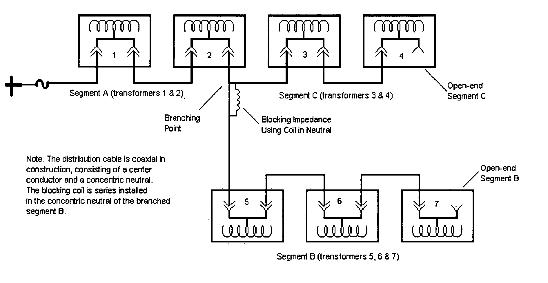
Blocking impedance

a technology of impedance and block, applied in the direction of electric variable regulation, process and machine control, instruments, etc., can solve the problem of limiting the usefulness of fault recorders and estimators for branched circuits, and achieve the effect of cost-effective utilization of fault recorders

Inactive Publication Date: 2005-03-17
ROCKWELL DANIEL J
View PDF11 Cites 27 Cited by
  • Summary
  • Abstract
  • Description
  • Claims
  • Application Information

AI Technical Summary

Benefits of technology

[0009] The purpose of this invention is to effectively utilize a fault recorder to estimate fault location on a branched circuit or circuit lacking a significant change in impedance at a desirable location. When a circuit is branched or lacks a significant change in impedance, an impedance can be introduced into the circuit. The purpose of the added impedance is to control the path taken by the traveling waves used for fault location estimation. This added impedance is essentially a blocking impedance whose purpose is to present a sufficient impedance on non-faulted connected lines so as to effectively block a majority of the fault signals from enteri

Problems solved by technology

This limits the usefulness of a fault rec

Method used


Image

  • Blocking impedance
  • Blocking impedance
  • Blocking impedance

Examples


Embodiment Construction

[0020] If the circuits of FIG. 1 and 2 are fed from underground rather than overhead, there is no reflection point for the traveling waves at the fuse or feed point. Significant impedance however can be readily introduced into the circuit at the feed point to create a point of reflection for the traveling waves. This impedance can be created using components such as a resistor, inductor or ferrite. The impedance should be sufficient to cause a majority of the traveling wave to reflect back toward the fault location.

[0021] The blocking impedance can be achieved using a resistor, inductor, ferrite or similar passive device in the neutral line at the desired location. A resistor is not a practical solution in terms of size and cost, when designed for a power distribution system. An inductor could be used, but would need to be designed to handle normal circuit conditions as well as fault conditions. Under fault conditions the inductor would be subjected to currents many times higher th...


PUM


Abstract

A power line distribution includes one or more impedance devices coupled to the neutral conductor of the power line distribution to segment the power line distribution for fault detection.

Description

CROSS REFERENCE TO RELATED APPLICATIONS [0001] This application is related to and claims the benefit of U.S. Provisional Application No. 60 / 319,745 entitled MULTI-HOP BRIDGE FOR TRANSFERRING DATA IN A WIRELESS NETWORK filed on Dec. 2, 2002.BACKGROUND [0002] High-voltage underground power distribution circuits are configured in a number of different configurations. Often a single-phase underground distribution system is configured as a fused radial-circuit (see FIG. 1) or as a fused loop-circuit (see FIG. 2). The distribution circuit could also be configured in a more complex configuration consisting of branches (see FIG. 3). A branched circuit could take on any form. [0003] A transient waveform is generated at the fault site on the initiation of a cable fault. This transient waveform or traveling wave, starts at the fault site and travels in both directions away from the fault. The traveling waves in either section of the circuit reflect between the fault location and a significant ...

Claims


Application Information

Patent Timeline
IPC IPC(8): G01R31/08H02H3/18
CPCG01R31/085
Inventor ROCKWELL, DANIEL J.
Owner ROCKWELL DANIEL J
Why Eureka
Try Eureka