
Tubular fuse component with end caps with a hermetically sealing plastic sealing body insert

a tube fuse and end cap technology, applied in the direction of basic electric elements, electric devices, emergency protective devices, etc., can solve the problems of unfavorable use, unfavorable use, and step increase in the cavity of the fuse component,

Active Publication Date: 2005-03-17
WICKMANN WERKE
View PDF14 Cites 18 Cited by
  • Summary
  • Abstract
  • Description
  • Claims
  • Application Information

AI Technical Summary

Benefits of technology

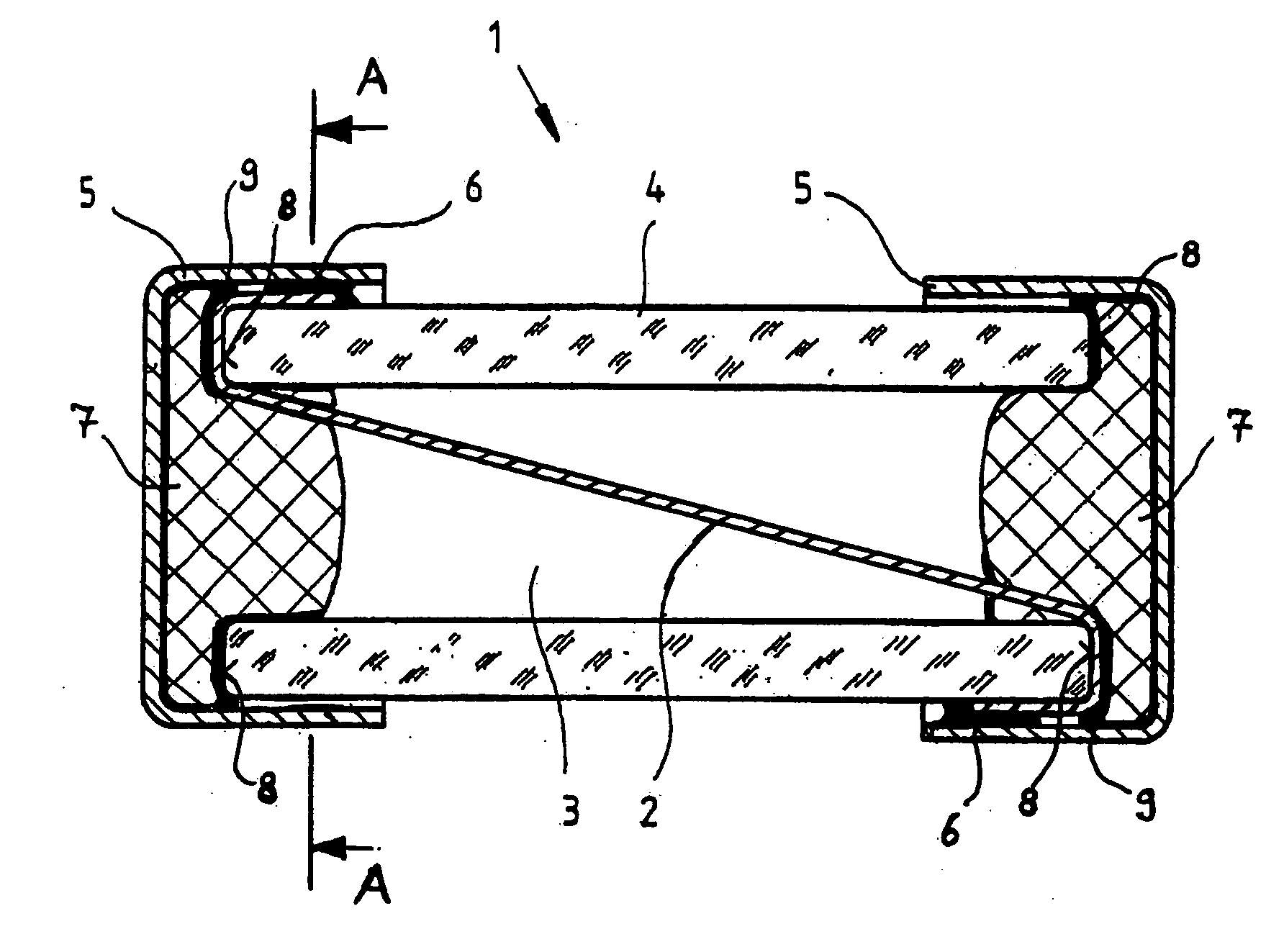
[0009] The fuse component in accordance with the invention is a component of the type referred to above, which is characterized in that inserted at at least one of the two ends of the tube in a gap between the cap base of the end cap and the end surface of the tube and in a portion of the cavity of the tube adjoining the cap base there is a sealing body of plastic material, which is predominantly elastically compressible but is at the same time capable of creep (in the sense of being flowable), whereby the sealing body has been compressed between the end surface and the cap base when positioning the end cap during the manufacture of the fuse component. The sealing body, which is compressed during insertion, then attempts to expand again, whereby it expands primarily in to the interior of the tube. If a sudden pressure increase occurs in the cavity shortly after its insertion during the manufacturing process as a result of a manufacturing step which results in a temperature increase in the cavity, it can occur that this overpressure reaches equilibrium into the external surroundings via a temporarily formed passage between the tube, the sealing body and the end cap. As a result of the fact that the plastic material is capable of creep, the passages thus formed and also any remaining gaps between the tube, the end cap and the fusible conductor inserted between them is closed by the flowing in of the plastic material. After a predetermined time of equilibrium or storage, a hermetic seal of the cavity of the tube thus forms. The fuse component in accordance with the invention also permits relatively simple manufacture because, instead of some liquid sealing material, a substantially solid sealing body is used, the shape of which can be previously matched to the dimensions of the end cap.
[0011] In the method in accordance with the invention for manufacturing a fuse component, a fusible conductor is firstly introduced into the interior of a cylindrical tube, whereby both of its ends are passed around the end surfaces of the tube onto the outer wall of the tube. End caps are then positioned on the ends of the tube with the ends of the fusible conductor passed around the end surfaces. An electrical contact between the end caps and the ends of the fusible conductor is thus formed. A sealing body of a plastic material, which is predominantly elastically compressible and at the same time capable of creep, is then introduced between the inner base of at least one of the two end caps and the end surface of the tube directed towards the inner base, whereby the sealing body is compressed when positioning the end cap. The fuse component is then subjected to a heat treatment at temperatures above 150° C. in order to ensure an electrical contact and / or to mechanically connect the end caps to the tube. Finally a hermetic seal of the interior forms as a result of creep (slow flowing) of the material of the sealing body. It is ensured in this manufacturing process that passages potentially forming in the heat treatment step are subsequently closed again by material flowing into them. The method in accordance with the invention permits, in a simple manner, the manufacture of fuse components with a hermetic seal of their interior.

Problems solved by technology

With a fuse component with a hermetically sealed cavity and an air or gas filling, the energy supplied by the arc results in a sudden, step increase in the pressure in the cavity of the fuse component.
Of disadvantage, however, with a fuse component with a hermetically sealed cavity is the fact that the pressure increase in the cavity is also produced if the fuse component is heated from the exterior, for instance in the manufacturing process.
The pressure increase, associated with such heating, in the interior of the tube results in an undesired loading of the fuse component and possibly in the formation of a pressure balancing passage (capillary passage) between the cavity in the tube and the surroundings through the gap between the tube and the end cap.

Method used


Image

  • Tubular fuse component with end caps with a hermetically sealing plastic sealing body insert
  • Tubular fuse component with end caps with a hermetically sealing plastic sealing body insert

Examples


Embodiment Construction

)

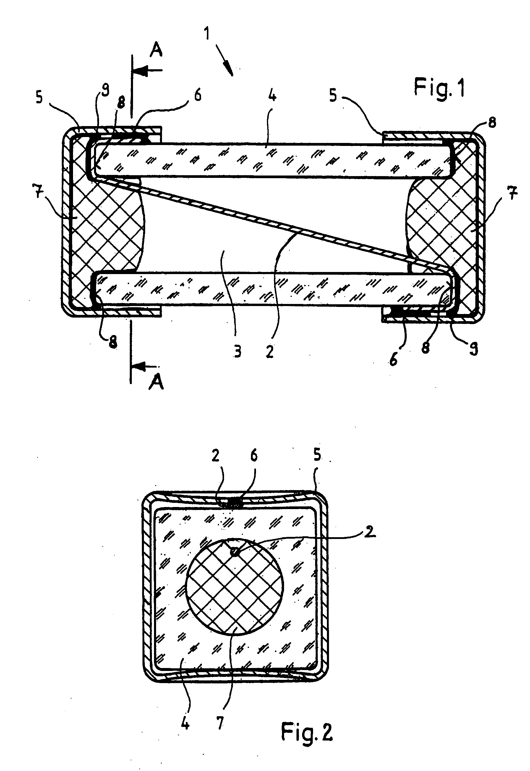
[0015] In the schematic longitudinal sectional view of FIG. 1, a fuse component 1 is illustrated, which has a fusible conductor 2, which extends diagonally in an internal cavity 3 of a cylindrical tube 4. In the embodiment and also in all other embodiments of the invention, the fusible conductor 2 can be not only a wire with any desired cross sectional profile but also a fusible conductive wire wound about an insulating core. The tube 4 has a cylindrical shape, which can have any desired cross sectional profile. The cavity 3 is, for instance, of circular cylindrical shape. The tube 4 is manufactured from an electrically insulating material, for instance of glass, ceramic material or plastic material. In the illustrated exemplary embodiment, the fusible conductor 2 extends diagonally through the cavity 3. In other embodiments, other arrangements of the fusible conductor 2 in the cavity 3 are possible. The fusible conductor 2 is preferably passed around the end surfaces 8 of the tube...


PUM


Abstract

A fuse component (1) has a fusible conductor (2) which extends in a gas filled cavity (3) within a cylindrical tube (4) between two end surfaces (8). Two end caps (5) of an electrically conductive material are applied to the ends of the tube (4) so that an electrical contact is produced with the fusible conductor (2). At at least one of the two ends of the tube (4), a sealing body of a plastic material, which is predominantly elastically compressible but at the same time capable of creep, is introduced into a gap between the base of the end cap and the end surface (8) of the tube (4) and into a portion of the cavity adjacent to the cap base. The sealing body has been compressed between the end surface (8) and the cap base during the manufacture of the fuse component (1) when positioning the end cap (5). The compressed sealing body (7) attempts to expand again, whereby it expands principally into the cavity (3). If a sudden pressure rise occurs in the cavity shortly after its introduction during the manufacturing process as a result of a temperature increase, it can occur that this overpressure balances out into the external surroundings via a temporarily formed passage between the tube, the sealing body and the end cap. The passage which is formed is then sealed again as a result of the ability of the plastic material to creep.

Description

BACKGROUND OF THE INVENTION [0001] The invention relates to a fuse component with a fusible conductor, which extends within a gas filled cavity in a cylindrical tube between two end surfaces of the tube, two end caps of an electrically conductive material being applied to the two ends of the tube such that a respective electrical contact with the fusible conductor is produced. The invention further relates to a method of manufacturing such a fuse component. [0002] Tubular fuse components of the type referred to above have been known for a long time. There are, for instance, fuse components, in which the cylindrical tube consists of a ceramic material and has a circular cylindrical internal cavity and a rectangular outer contour with rounded edges. The fusible conductor is, for instance, a wire, which extends diagonally within the cavity such that it contacts the walls of the tube merely at its ends. The wire of the fusible conductor is passed around the end surfaces of the tube, whe...

Claims


Application Information

Patent Timeline
IPC IPC(8): H01H85/00H01H85/041H01H85/157
CPCH01H85/003H01H85/157H01H85/0418
Inventor RICHTER, LUDGERBAUS, ANDREASJOLLENBECK, ANDRE
Owner WICKMANN WERKE
Learn More