Heat dissipating circulatory system with sputtering assembly

Inactive Publication Date: 2005-03-17
HON HAI PRECISION IND CO LTD
View PDF21 Cites 0 Cited by
  • Summary
  • Abstract
  • Description
  • Claims
  • Application Information

AI Technical Summary

Benefits of technology

[0008] Accordingly, an object of the present invention is to provide a heat dissipating circulatory system which can achieve timely and efficient heat exchange.
[0010] The operating fluid is directly sputtered onto the fin via the nozzles. Thus, direct heat exchange occurs between the operating fluid and the fin, unlike in conventional heat dissipating devices. This ensures that the heat exchange between the operating fluid and the fins is timely and efficient, and improves a heat dissipating efficiency of the heat dissipating circulatory system.

Problems solved by technology

Generally, however, the heat dissipating efficiency of the fan is relatively poor.
Heat produced in the electronic components cannot be dissipated timely and efficiently.
Furthermore, the fan is prone to produce noise during operation.
Because the heat exchange between the operating fluid and the fin must be via the first pipe of the fin, the heat dissipating device does not provide direct heat exchange.
This effectively reduces the efficiency of the heat dissipating device.

Method used


Image

  • Heat dissipating circulatory system with sputtering assembly
  • Heat dissipating circulatory system with sputtering assembly
  • Heat dissipating circulatory system with sputtering assembly

Examples


Embodiment Construction

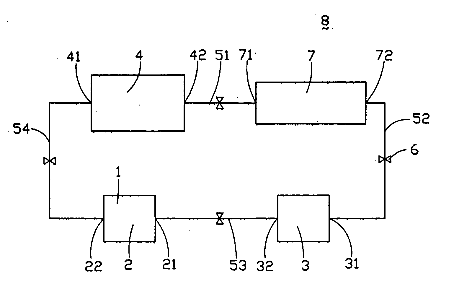
[0015] Referring to FIG. 1, a heat dissipating circulatory system 8 of the present invention comprises a pool 7 as a reservoir for receiving an operating fluid (not shown), a pump 3 as a circulating driver, a heat spreader 2, and a condenser 4. A first pipe 51 interconnects an output end 42 of the condenser 4 and an input end 71 of the pool 7. A second pipe 52 interconnects an output end 72 of the pool 7 and an input end 31 of the pump 3. A third pipe 53 interconnects an output end 32 of the pump 3 and an input end 21 of the heat spreader 2. A fourth pipe 54 interconnects an output end 22 of the heat spreader 2 and an input end 41 of the condenser 4.

[0016] The pump 3 is used to drive the operating fluid to flow in a same direction through the heat dissipating circulatory system 8. In the preferred embodiment, the pump 3 is a micro pump.

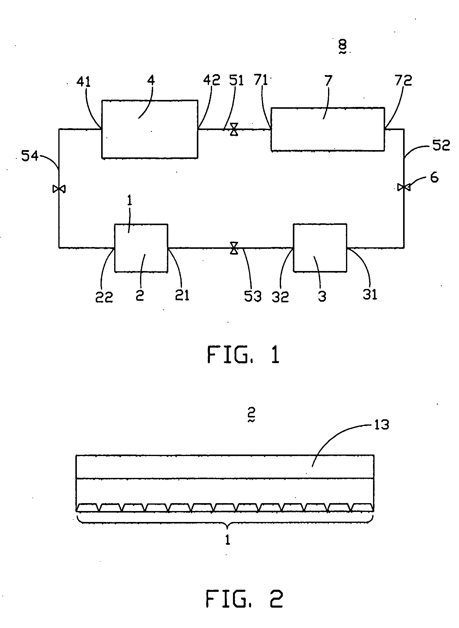
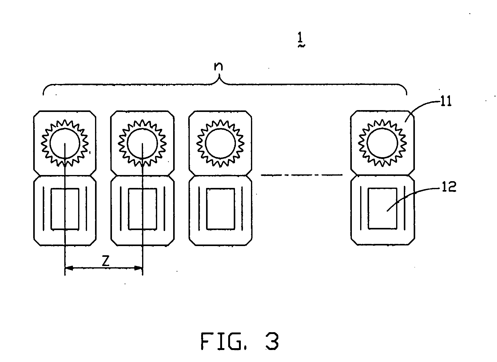
[0017] Referring to FIGS. 2 and 3, the heat spreader 2 comprises a fin 13 and a corresponding liquid sputtering assembly 1. The fin 13 is flat and ...


PUM


Abstract

A heat dissipating circulatory system (8) includes a pool (7) for receiving an operating fluid, a pump (3), a heat spreader (2) and a condenser (4). A first pipe (51) interconnects an output end (42) of the condenser and an input end (71) of the pool. A second pipe (52) interconnects an output end (72) of the pool and an input end (31) of the pump. A third pipe (53) interconnects an output end (32) of the pump and an input end (21) of the heat spreader. A fourth pipe (54) interconnects an output end (22) of the heat spreader and an input end (41) of the condenser. The heat spreader includes a fin (13) and a liquid sputtering assembly (1). The liquid sputtering assembly includes a plurality of nozzles (11) and drivers (12). The operating fluid is directly sputtered onto the fin, thereby providing direct heat exchange.

Description

BACKGROUND OF THE INVENTION [0001] 1. Field of the Invention [0002] The invention relates generally to heat dissipating circulatory systems for dissipating heat from heat-generating apparatus or components, and more particularly to a heat dissipating circulatory system with a sputtering assembly and using a liquid operating fluid. [0003] 2. Description of the Prior Art [0004] The operating speed of electronic apparatus such computers, printers and copiers is becoming progressively higher, and is due in large part to the increase in electronic transmissions speeds of components of these apparatus. Correspondingly, the heat dissipation requirements of these components are increasing too. In many contemporary applications, a fan is fixed on or near such electronic components to dissipate heat. The fan dissipates heat by utilizing air as the operating medium. Generally, however, the heat dissipating efficiency of the fan is relatively poor. Heat produced in the electronic components can...

Claims


Application Information

Patent Timeline
IPC IPC(8): H01L23/473H05K7/20
CPCH01L23/4735H05K7/20345H01L2924/0002H01L2924/00
Inventor CHEN, GA-LANELEU, CHARLES
Owner HON HAI PRECISION IND CO LTD
Why Eureka
Try Eureka