Thermal interface material characterizing system

a thermal interface and characterizing system technology, applied in the field of material testing, can solve the problems of limiting performance, shortening the life of components, and confusing end-users

Inactive Publication Date: 2005-03-17
HEWLETT PACKARD DEV CO LP
View PDF14 Cites 42 Cited by
  • Summary
  • Abstract
  • Description
  • Claims
  • Application Information

AI Technical Summary

Benefits of technology

An advantage of the present invention is that a test system is provided for the uniform characterization of thermal interface materials.
Another advantage of the present invention is that an automated method is provided for the characterization of thermal inte...

Problems solved by technology

High temperatures can shorten component life and limit performance.
But manufacturers use a variety of ways to report material thermal resistance, such confuse end-users.
A disadvantage of this conventional technique is it requires constant operator intervention to obtain a set of meaningful data.
Many suppliers have also either modified or incorrectly applied the standard method in such a way that it is difficult for...

Method used


Image

  • Thermal interface material characterizing system
  • Thermal interface material characterizing system
  • Thermal interface material characterizing system

Examples


Embodiment Construction

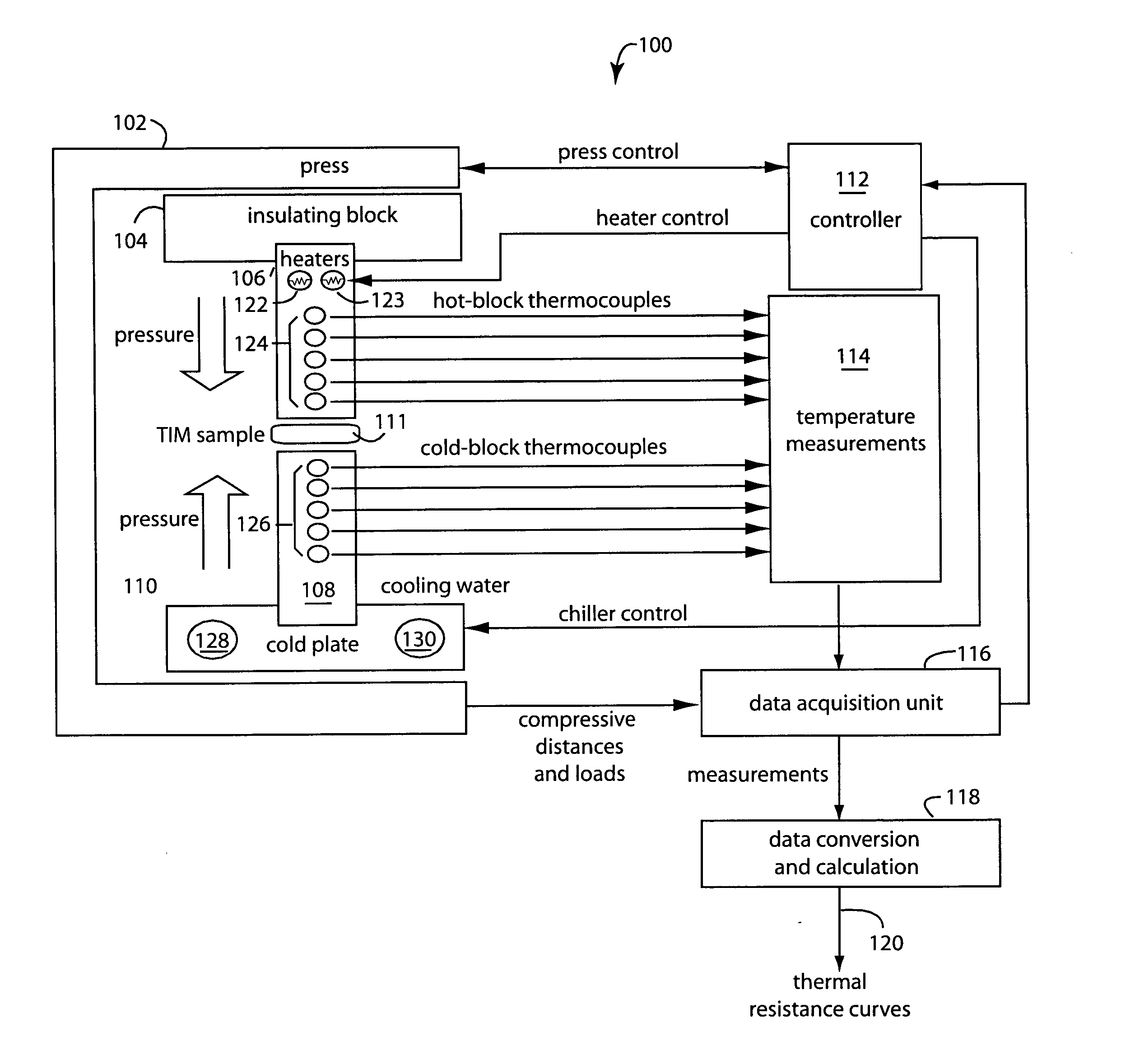
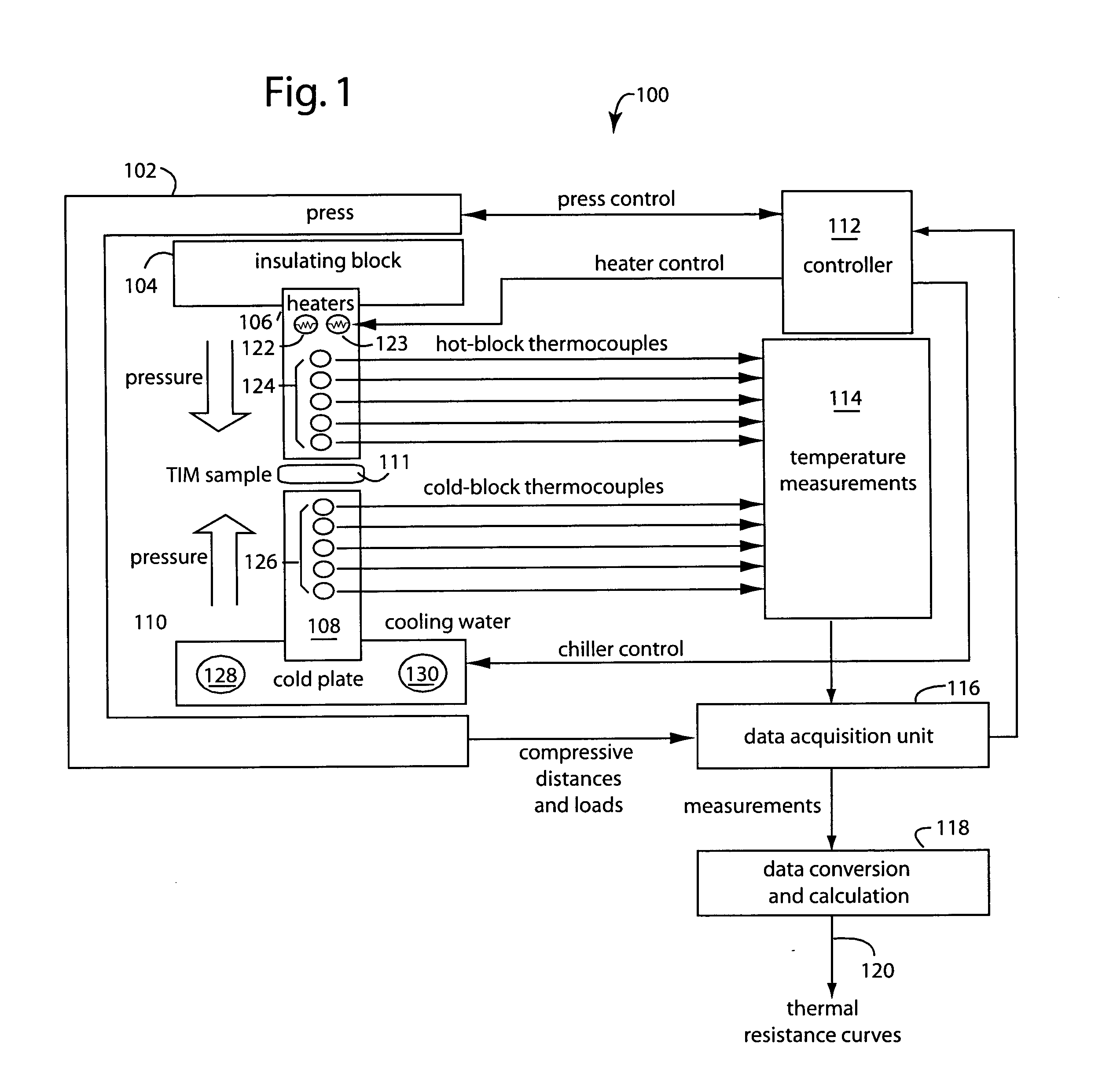
FIG. 1 illustrates a thermal interface material (TIM) test system embodiment of the present invention, and is referred to herein by the general reference numeral 100. The system 100 comprises a programmable press 102 in which are mounted a heat insulating block 104, a hot block 106, a cold block 108, and a cold plate 110. A “sample” TIM 111 is squeezed between the hot and cold blocks 106 and 108 during characterization. It is important that the pressure being applied remains constant even while TIM 111 expands and contracts over its programmed temperature excursions. An INSTRON 5566 can be used, as marketed by Instron Corporation, 100 Royall Street, Canton, Mass., 02021, USA. A gauge is useful for measuring the thickness of the TIM 111 at room temperature and at a test temperature.

A controller 112 manages how the programmable press 102 will operate during tests of the TIM, e.g., the pressures and durations applied. The controller 112 further adjusts the heat being applied and the c...


PUM


Abstract

An automated test method characterizes the performance of commercially available thermal interface materials (TIM) for electronic cooling. Such automated internal test vehicle provides an independent study of various TIM's. A spectrum of materials are preferably tested using automated methods so the results are reported in a consistent way. Such reports simplify the comparison and selection of appropriate TIM material for various end-user applications. Such automated test method is observed to be faster and easier to use. It requires minimal operator intervention during the test.

Description

FIELD OF THE INVENTION The present invention relates to material testing, and more specifically to a device and method for characterizing thermal interface materials while being subjected to automated pressure loads and thermal gradients. BACKGROUND OF THE INVENTION Modern high-speed, high performance systems require good thermal management. High temperatures can shorten component life and limit performance. So good system thermal performance must be included at the start of any new design. The power density of circuits has been increasing as the size of electronics continues to shrink. Heatsinks have been a traditional way to help semiconductor devices to dissipate heat into the environment. Such heatsinks are typically made of finned aluminum and their bases are thermally coupled to the substrate of the semiconductor device. Very often, the heatsink must be electrically isolated from the substrate of the semiconductor device, so mica insulators and silicon gel are used between ...

Claims


Application Information

Patent Timeline
IPC IPC(8): G01N3/02G01N3/18G01N11/00G01N25/18
CPCG01N3/18G01N11/00G01N2203/023G01N2203/0222G01N25/18
Inventor SHIH, CHIH C.BASH, CULLEN E.
Owner HEWLETT PACKARD DEV CO LP
Why Eureka
Try Eureka