Supercharge Your Innovation With Domain-Expert AI Agents!

X-ray tube and method of producing the same

a technology of x-ray tube and x-ray tube, which is applied in the direction of x-ray tube electrodes, electrical devices, electric discharge tubes, etc., can solve the problems of difficult to accurately secure the metal tube to the vacuum envelope, large effort is needed to accurately fix the target supporter to the metal tube, and it is difficult in the conventional x-ray tube to set the x-ray focus point to an extremely small point, etc., to achieve accurate fuse bonding and high accuracy

Inactive Publication Date: 2005-03-17
HAMAMATSU PHOTONICS KK
View PDF3 Cites 8 Cited by
  • Summary
  • Abstract
  • Description
  • Claims
  • Application Information

AI Technical Summary

Benefits of technology

The present invention provides an X-ray tube and a method for making it that can accurately position the components and set the X-ray focus point to an extremely small point. The X-ray tube includes an envelope main body, a valve, and a metal tube, and the position of the electron generating unit and the target can be determined accurately. The X-ray tube can be easily made with high accuracy in position and can keep the vacuum envelope air-tight. The method for making the X-ray tube involves fuse-bonding the inner cylinder portion of the valve to the end portion of the metal tube and securely positioning the target supporter in the metal tube.

Problems solved by technology

However, it has been difficult to secure the metal tube to the vacuum envelope accurately when the inner cylinder portion and the metal tube are fuse-bonded to each other in the conventional X-ray tube as described above.
Therefore, much effort is needed to fix the target supporter to the metal tube accurately.
As described above, it has been difficult in the conventional X-ray tube to set the X-ray focus point to an extremely small point due to the dimensional accuracy and fabrication accuracy in the making process.

Method used


Image

  • X-ray tube and method of producing the same
  • X-ray tube and method of producing the same
  • X-ray tube and method of producing the same

Examples


Embodiment Construction

[0023] Preferred embodiments of the present invention will be described hereunder in detail with reference to the accompanying drawings. To facilitate the comprehension of the explanation, the same reference numerals denote the same parts, where possible, throughout the drawings, and a repeated explanation will be omitted.

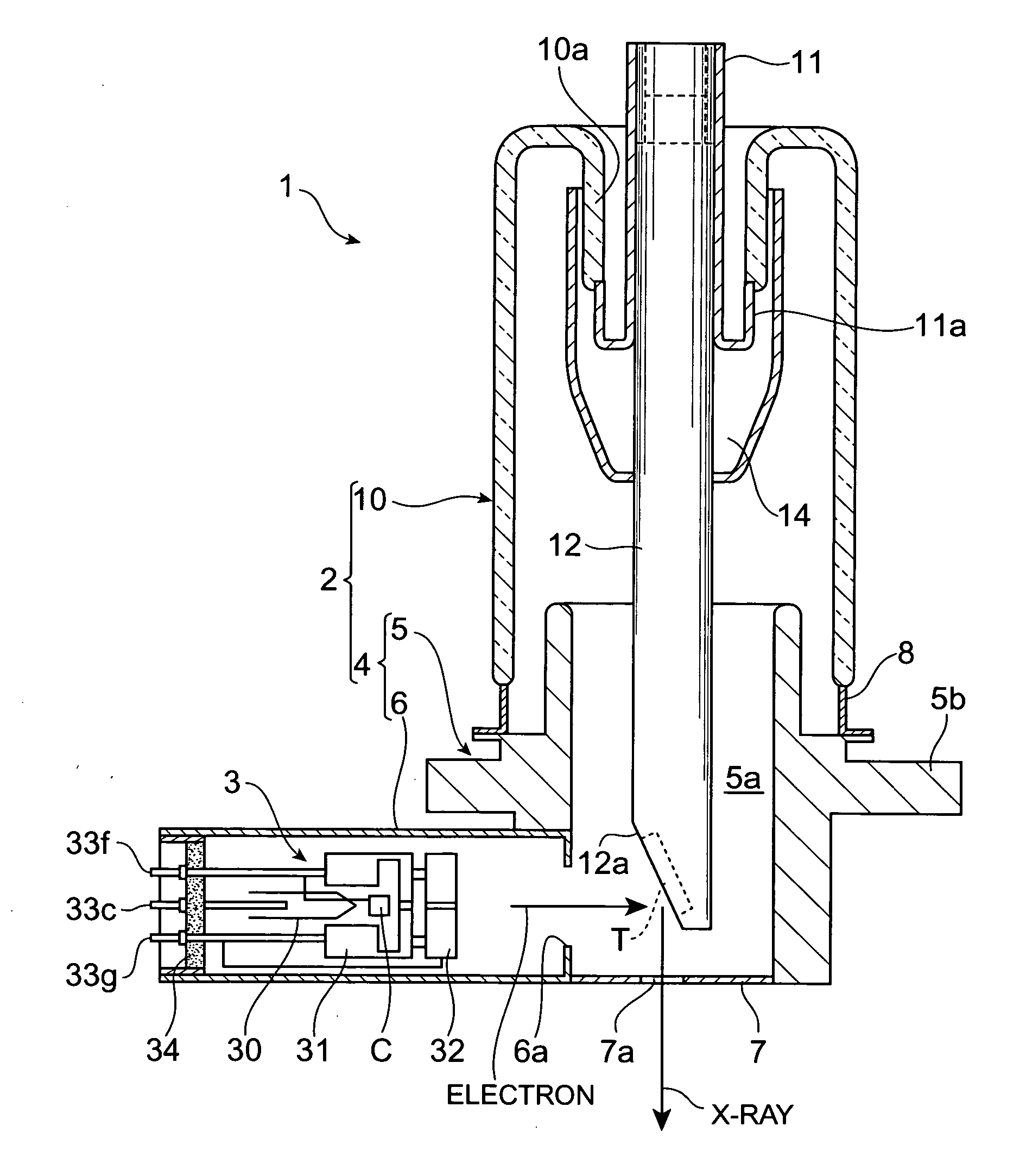
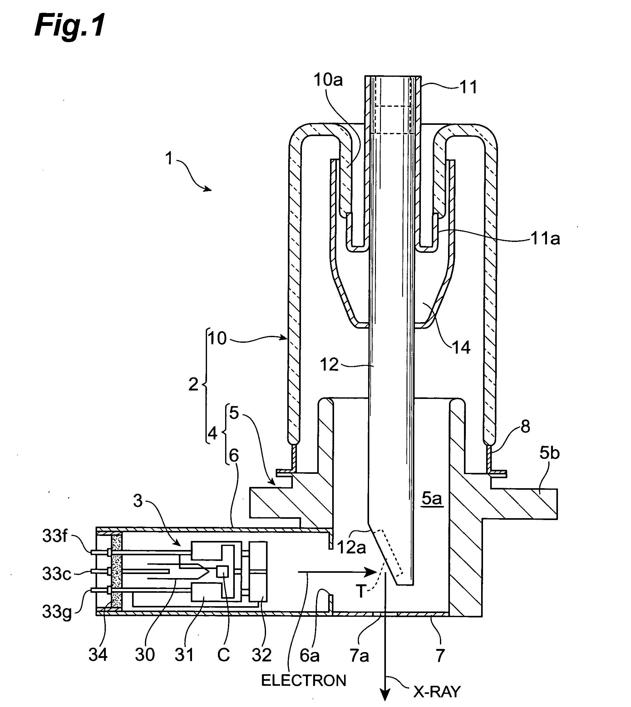
[0024]FIG. 1 is a cross-sectional view showing a preferred embodiment of an X-ray tube according to the present invention. The X-ray tube 1 shown in FIG. 1 is suitably used as an X-ray generating source of an X-ray inspection apparatus, for example, and it comprises of a vacuum envelope 2, an electron generating unit (electron gun) 3, and a target T. The electron generating unit 3 has a cathode C which is a porous tungsten or the like, impregnated with BaO or the like. The target T is a laminated X-ray generating films formed of tungsten or the like through a protection layer on a carbon layer. The electron generating unit 3 and the target T are accommodated in th...


PUM


Abstract

An X-ray tube 1 comprises of a valve 10 joined to an envelope main body 4 at one end side thereof and having an inner cylinder portion 10a extending inwardly at the other end side thereof, a metal tube 11 having an extension portion 11a abutting against the inner cylinder portion 10a on the outer periphery of one end side thereof and projecting to the outside of the valve 10 through the inner cylinder portion 10a at the other end side thereof, and a target supporter 12 supporting a target T at the one end side thereof and inserted into the metal tube 11 at the other side thereof. The inner cylinder portion 10a of the valve 10 and the extension portion 11a of the metal tube 11 are fuse-bonded to each other, and the target supporter 12 is welded to the end portion of the metal tube 11 projecting from the valve 10.

Description

FIELD OF THE ART [0001] The present invention relates to an X-ray tube and a method for making the X-ray tube, and particularly to a micro-focus X-ray tube in which an X-ray focus point can be remarkably finely set, and a method for making the X-ray tube. BACKGROUND ART [0002] An X-ray tube outputs X-rays by inpinging electrons on a target, and conventionally has been utilized as an X-ray generator such as an X-ray inspection apparatus or the like which is used for nondestructive inspection, non-contact inspection or the like. For a sample of Such X-ray tube, one disclosed in Japanese Unexamined Examined Utility Model Application No. H03-110753 is well known. The X-ray tube described in this publication has a vacuum envelope molded insulating material such as glass or the like in a substantially cylindrical shape. Both end portions of the vacuum envelope are inwardly folded over the overall peripheries thereof, and thus inner cylinder portions extending to the inside of the envelope...

Claims


Application Information

Patent Timeline
Patent Type & Authority Applications(United States)
IPC IPC(8): H01J9/14H01J35/04H01J35/08H01J35/16
CPCH01J35/16
Inventor INAZURU, TUTOMUOKADA, TOMOYUKI
Owner HAMAMATSU PHOTONICS KK
Features
  • R&D
  • Intellectual Property
  • Life Sciences
  • Materials
  • Tech Scout
  • Unparalleled Data Quality
  • Higher Quality Content
  • 60% Fewer Hallucinations
Learn More