Radio receiver

a receiver and radio technology, applied in the field of radio receivers, can solve the problems of reducing the sound quality of the audio output, the circuit cannot be synchronized,

Inactive Publication Date: 2005-03-17
RICOH KK +1
View PDF3 Cites 4 Cited by
  • Summary
  • Abstract
  • Description
  • Claims
  • Application Information

AI Technical Summary

Benefits of technology

[0012] The present invention is devised to solve the problem described above. Accordingly, an object of the invention is to make it possible to suppress the beat signal generated by asynchronization between the clock signal used in the CCD delay circuit and the clock signal used in the stereo demodulation circuit.

Problems solved by technology

Consequently, a problem arises that the clock signal used in the CCD delay circuit can not be synchronized with the clock signal used in the stereo demodulation circuit, thereby generating a beat signal in the output of the stereo demodulation circuit.
The beat signal can cause fluctuating sound localization to thereby reduce the sound quality of the audio output.

Method used


Image

  • Radio receiver
  • Radio receiver
  • Radio receiver

Examples


Embodiment Construction

[0017] An embodiment of the present invention will be described below with reference to the accompanying drawings.

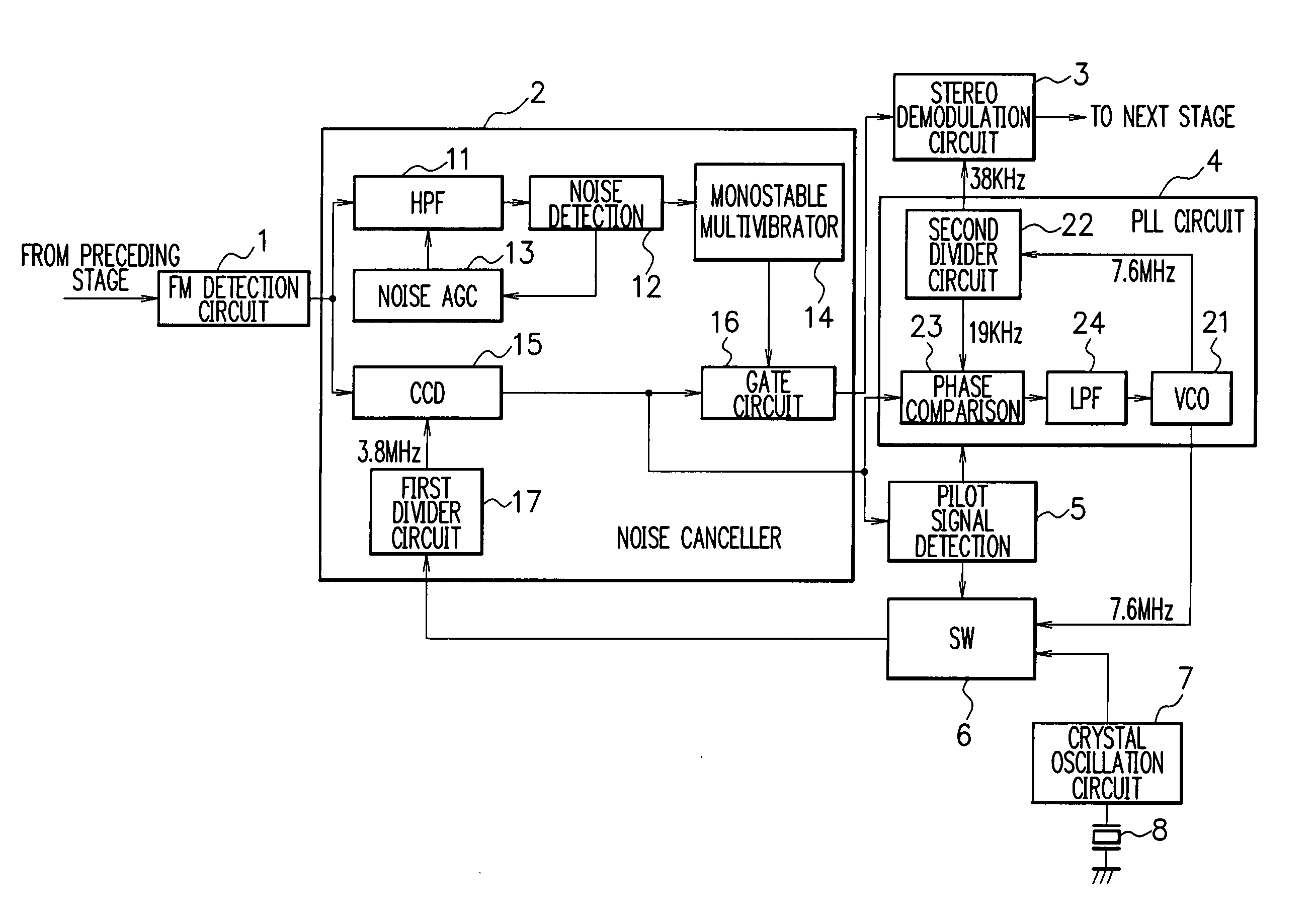
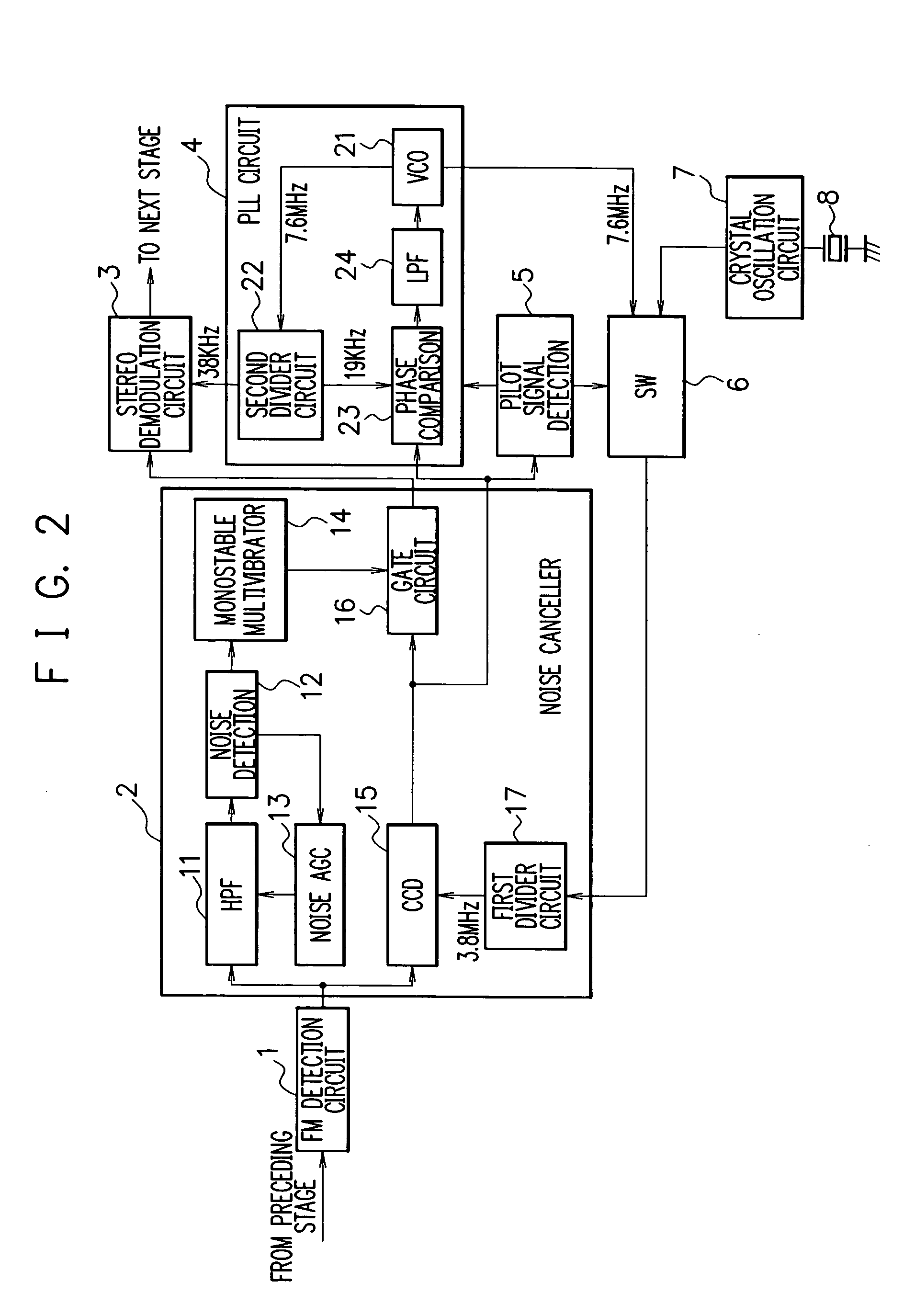
[0018]FIG. 2 is a schematic diagram showing the configuration of a main part of an FM radio receiver according to the present embodiment. Referring to FIG. 2, an FM detection circuit 1 performs a detection process with respect to an intermediate frequency signal generated from an FM broadcast signal to output a composite signal. Similarly to the circuit shown in FIG. 1, the intermediate frequency signal supplied to the FM detection circuit 1 is generated through a high frequency amplifier circuit, a frequency conversion circuit and an intermediate frequency amplifier circuit.

[0019] A noise canceller 2 removes a pulse noise from the composite signal output from the FM detection circuit 1 to output a signal free of the pulse noise to a stereo demodulation circuit 3. The noise canceller 2 includes a high pass filter (HPF) 11, a noise detection circuit 12, a noise AGC (Aut...


PUM


Abstract

A radio receiver includes a noise canceller (2) for removing a pulse noise from a composite signal from an FM detection circuit (1), a stereo demodulation circuit (3) for demodulating the output signal of the noise canceller (2) to reproduce a stereo signal, and a VCO (21) for outputting a clock signal as an origin of a clock signal used in the stereo demodulation circuit (3). A clock signal used in a CCD (15) of the noise canceller (2) is generated based on a clock signal output from the VCO (21), so as to synchronize the phase of the signal used in the CCD (15) with the phase of the clock signal used in the stereo demodulation circuit (3), thereby suppressing generation of a beat signal in the output of the stereo demodulation circuit (3).

Description

FIELD OF THE INVENTION [0001] The present invention relates to a radio receiver, and more particularly to a radio receiver including a function of a noise canceller for removing, by controlling the opening and closing of a gate, a pulse noise from a composite signal obtained by FM-detecting an intermediate frequency signal. BACKGROUND OF THE INVENTION [0002] Generally, in an FM radio receiver, various measures against noises are taken to improve the sound quality. A typical configuration of a conventional FM radio receiver will be described below. FIG. 1 is a diagram showing an overall configuration of a conventional FM radio receiver. An FM radio receiver 100 shown in FIG. 1 includes: an antenna 101; a high frequency amplifier circuit 102; a frequency conversion circuit 103; a PLL (Phase Locked Loop) circuit 104; an intermediate frequency amplifier circuit 105; an FM detection circuit 106; a noise canceller 107; a stereo demodulation circuit 108; an audio adjustment circuit 109; a ...

Claims


Application Information

Patent Timeline
Patent Type & Authority Applications(United States)
IPC IPC(8): H04B1/16
CPCH04B1/1661
Inventor KARASUDANI, MUNEHIRO
Owner RICOH KK
Why Eureka
Try Eureka